Working Principle of DS18B20 Smart Sensor
DS18B20 intelligent temperature sensor working principle and timing:
DS18B20 is the latest improved smart temperature sensor launched by DALLAS Semiconductor Company in the United States after DS1820. Compared with traditional thermistors, it can directly read the measured temperature and can achieve 9 to 12-digit digital value reading through simple programming according to actual requirements. 9-bit and 12-bit digital quantities can be completed within 93.75 ms and 750 ms respectively, and the information read from DS18B20 or written to DS18B20 only requires one port line (single-wire interface) to read and write. The temperature conversion power comes from the data bus, and the bus itself can also supply power to the connected DS18B20 without the need for an additional power supply. Therefore, using DS18B20 can make the system structure simpler and more reliable. It has great improvements over DS1820 in terms of temperature measurement accuracy, conversion time, transmission distance, resolution, etc., bringing users more convenient use and more satisfactory results.
1. Introduction to DS18B20
(1) Unique single-wire interface method: When DS18B20 is connected to the microprocessor, only one port line is needed to achieve two-way communication between the microprocessor and DS18B20.
(2) No external components are required during use.
(3) It can be powered by data line, voltage range: +3.0~ +5.5 V.
(4) Temperature measurement range: -55 ~ +125 ℃. The inherent temperature measurement resolution is 0.5 ℃.
(5) Digital reading mode of 9~12 digits can be realized through programming.
(6) Users can set non-volatile alarm upper and lower limits.
(7) Support multi-point networking function, multiple DS18B20 can be connected in parallel on the only three lines to achieve multi-point temperature measurement.
(8) Negative voltage characteristics: When the polarity of the power supply is reversed, the thermometer will not burn due to heat, but it will not work properly.
Temperature measurement principle of DS18B20
The temperature measurement principle of DS18B20 is shown in Figure 2. The oscillation frequency of the low temperature coefficient crystal oscillator in the figure is very little affected by temperature [1]. It is used to generate a fixed frequency pulse signal and send it to the subtraction counter 1. The oscillation frequency of high temperature coefficient crystal oscillators changes significantly with temperature changes. The generated signal is used as the pulse input of subtraction counter 2. There are also counting gates implicit in the figure. When the counting gate is opened, the DS18B20 counts the clock pulses generated by the low temperature coefficient oscillator to complete the temperature measurement. The opening time of the counting gate is determined by a high temperature coefficient oscillator. Before each measurement, first put the base number corresponding to -55 ℃ into the subtraction counter 1 and the temperature register respectively. The down counter 1 and the temperature register are preset at a base value corresponding to -55°C. Subtraction counter 1 performs subtraction counting on the pulse signal generated by the low temperature coefficient crystal oscillator. When the preset value of subtraction counter 1 decreases to 0, the value of the temperature register will be increased by 1, and the preset value of subtraction counter 1 will be reloaded. Subtraction counter 1 restarts counting the pulse signal generated by the low temperature coefficient crystal oscillator, and this cycle continues until subtraction counter 2 counts to 0, and then stops accumulating the temperature register value. At this time, the value in the temperature register is the measured temperature. The slope accumulator in Figure 2 is used to compensate and correct the nonlinearity in the temperature measurement process, and its output is used to correct the preset value of the subtraction counter. As long as the counting gate is not closed, the above process is repeated until the temperature register value reaches the measured temperature value. This is the temperature measurement principle of DS18B20.
In addition, since the DS18B20 single-line communication function is completed in time sharing, it has a strict time slot concept, so the read and write timing is very important. Various operations of the system on DS18B20 must be performed according to the protocol. The operation protocol is: initialize DS18B20 (send reset pulse) → send ROM function command → send memory operation command → process data. The timing diagram for various operations is the same as that of the DS1820.
DS18B20 working process and timing
The low temperature coefficient oscillator inside the DS18B20 is an oscillator whose oscillation frequency changes very little with temperature, providing a stable frequency counting pulse for counter 1.
The high temperature coefficient oscillator is an oscillator whose oscillation frequency is very sensitive to temperature and provides counter 2 with a counting pulse whose frequency changes with temperature.
Initially, the temperature register is preset to -55°C. Whenever counter 1 counts down from the preset number to 0, the temperature value registered in the temperature register increases by 1°C. This process is repeated until counter 2 reaches 0 and then stops.
Initially, counter 1 is preset with a preset value corresponding to -55°C. In the future, the preset number of each cycle of counter 1 is provided by the slope accumulator. In order to compensate for the non-linearity of the oscillator temperature characteristics, the preset number provided by the slope accumulator also changes accordingly with the temperature. The preset number of counter 1 is the number of counts required to increase the temperature register value by 1°C at a given temperature.
The comparator inside the DS18B20 determines the least significant bit of the temperature register in a rounded quantization manner. After counter 2 stops counting, the comparator converts the remaining counting value in counter 1 into a temperature value and compares it with 0.25°C. If it is lower than 0.25℃, the lowest bit of the temperature register is set to 0. If it is higher than 0.25℃, the lowest bit is set to 1. If it is higher than 0.75℃, the lowest bit of the temperature register is carried and then set to 0. In this way, the value of the temperature register obtained after comparison is the final temperature value read, and the last bit represents 0.5°C. The maximum rounding quantization error is ±1/2LSB, which is 0.25°C.
The temperature value in the temperature register is expressed in a 9-bit data format, the highest bit is the sign bit, and the remaining 8 bits represent the temperature value in two's complement form. At the end of the temperature measurement, these 9-bit data are transferred to the first two bytes of the temporary storage memory, and the sign bit occupies the first byte. The 8-bit temperature data occupies the second byte.
DS18B20 uses unique temperature measurement technology when measuring temperature. The low temperature coefficient oscillator inside the DS18B20 can produce a stable frequency signal. Similarly, a high temperature coefficient oscillator converts the measured temperature into a frequency signal. When the counting gate is opened, DS18B20 counts, and the counting gate opening time is determined by the high temperature coefficient oscillator. There is also a slope accumulator inside the chip to compensate for frequency nonlinearity. The measurement results are stored in the temperature register. Under normal circumstances, the temperature value should be 9 bits, but because the sign bit is extended to the upper 8 bits, it is finally read out in 16-bit complement form.
The working process of DS18B20 generally follows the following protocol: initialization - ROM operation command - memory operation command - data processing
① Initialization
All processing on a single bus begins with an initialization sequence. The initialization sequence includes a reset pulse from the bus master, followed by a presence pulse from the slave device. The presence of the pulse lets the bus controller know that the DS1820 is on the bus and is ready to operate.
② ROM operation command
Once the bus master detects the presence of a slave device, it can issue one of the device ROM operation commands. All ROM operation commands are 8 bits long. The list of these commands is as follows:
Read ROM (read ROM)[33h]
This command allows the bus master to read the DS18B20's 8-bit product family code, unique 48-bit serial number, and 8-bit CRC. This command can only be used when there is only one DS18B20 on the bus. If there is more than one slave device on the bus, data collisions will occur when all slaves attempt to transmit at the same time (an open drain will produce a wired AND result).
Match ROM(match ROM)[55h]
This command is followed by a 64-bit ROM data sequence, allowing the bus master to address a specific DS18B20 on the multidrop bus. Only the DS18B20 that strictly matches the 64-bit ROM sequence can respond to subsequent memory operation commands. All slaves that do not match the 64-bit ROM sequence will wait for a reset pulse. This command can be used with single or multiple devices on the bus.
Skip ROM(skip ROM)[CCh]
In single-point bus systems, this command saves time by allowing the bus master to access memory operations without providing 64-bit ROM encoding. If there is more than one slave device on the bus and a read command is issued after the Skip ROM command, data conflicts will occur on the bus due to multiple slave devices sending data at the same time.
Search ROM(Search ROM)[F0h]
When the system starts working, the bus master may not know the number of devices on the single-wire bus or its 64-bit ROM code. The Search ROM command allows the bus controller to identify the 64-bit codes of all slaves on the bus by process of elimination.
Alarm Search (alarm search) [ECh]
The flow of this command is the same as the search ROM command. However, the DS18B20 will only respond to this command if an alarm occurred during the most recent temperature measurement. The alarm condition is defined as the temperature being higher than TH or lower than TL. As soon as the DS18B20 is powered on, the alarm condition remains set until another temperature measurement shows a non-alarm value or the TH or TL setting is changed so that the measured value is once again within the allowed range. The trigger value stored in EEPROM is used for alarms.
③ Memory operation command
Write Scratchpad (write scratchpad) [4Eh]
This command writes data to the temporary register of DS18B20, starting at address 2. The next two bytes written will be stored in the scratchpad at address locations 2 and 3. A reset command can be issued at any time to abort writing.
Read Scratchpad [BEh]
This command reads the contents of the scratchpad. Reading will start from byte 0 and continue until the 9th (byte 8, CRC) byte is read. If it does not want to read all bytes, the controller can issue a reset command at any time to abort the read.
Copy Scratchpad (copy scratchpad) [48h]
This command copies the contents of the temporary register to the E2 memory of DS18B20, that is, stores the temperature alarm trigger byte in non-volatile memory. If the bus controller issues a read time gap after this command and the DS18B20 is busy copying the scratchpad to E2 memory, the DS18B20 will output a "0". If the copy is completed, DS18B20 will output "1". If parasitic power is used, the bus controller must initiate a strong pull-up immediately after this command is issued and maintain it for at least 10ms.
Convert T (temperature conversion) [44h]
This command initiates a temperature conversion without requiring additional data. The temperature conversion command is executed, and then the DS18B20 remains in a wait state. If the bus controller issues a read time gap after this command and the DS18B20 is busy doing time conversion, the DS18B20 will output "0" on the bus and "1" if the temperature conversion is completed. If parasitic power is used, the bus controller must initiate a strong pull-up immediately after issuing this command and maintain it for 500ms.
Recall E2 (Recall E2) [B8h]
This command resets the value of the temperature trigger stored in E2 to the temporary memory. This recall operation also occurs automatically when the DS18B20 is powered on, so as soon as the device is powered on, there is valid data in the temporary memory. After this command is issued, for the first read data time slice issued, the device will output a temperature conversion busy flag: "0" = busy, "1" = ready.
Read Power Supply [B4h]
For the time slice of the first read data issued after this command is sent to the DS18B20, the device will give a signal of its power mode: "0" = powered by a parasitic power supply, "1" = powered by an external power supply.
④ Process data
The high-speed scratchpad memory of DS18B20 consists of 9 bytes, and its allocation is shown in Figure 3. When the temperature conversion command is issued, the converted temperature value is stored in the 0th and 1st bytes of the cache memory in two-byte complement form. The microcontroller can read the data through the single-wire interface, with the low bit in front and the high bit in the back.
Figure 3 Cache memory allocation diagram
DS18B20 Temperature Data Sheet
The above table is the 12-bit data obtained after temperature acquisition and conversion by DS18B20. Stored in two 8-bit RAMs of DS18B20, the first 5 bits in binary are sign bits. If the measured temperature is greater than or equal to 0, these 5 bits are 0. Just multiply the measured value by 0.0625 to get the actual temperature. If the temperature is less than 0, these 5 bits are 1, and the measured value needs to be inverted, plus 1, and then multiplied by 0.0625 to get the actual temperature.
Example of temperature conversion calculation method:
For example, when DS18B20 collects the actual temperature of +125°C, the output is 07D0H, then:
Actual temperature=07D0H╳0.0625=2000╳0.0625=1250C.
For example, when DS18B20 collects the actual temperature of -55°C and outputs FC90H, the 11 data bits should be inverted and added by 1 to get 370H (the sign bit remains unchanged and is not included in the calculation), then:
Actual temperature=370H╳0.0625=880╳0.0625=550C.
DS18B20 is the latest improved smart temperature sensor launched by DALLAS Semiconductor Company in the United States after DS1820. Compared with traditional thermistors, it can directly read the measured temperature and can achieve 9 to 12-digit digital value reading through simple programming according to actual requirements. 9-bit and 12-bit digital quantities can be completed within 93.75 ms and 750 ms respectively, and the information read from DS18B20 or written to DS18B20 only requires one port line (single-wire interface) to read and write. The temperature conversion power comes from the data bus, and the bus itself can also supply power to the connected DS18B20 without the need for an additional power supply. Therefore, using DS18B20 can make the system structure simpler and more reliable. It has great improvements over DS1820 in terms of temperature measurement accuracy, conversion time, transmission distance, resolution, etc., bringing users more convenient use and more satisfactory results.
 |
 |
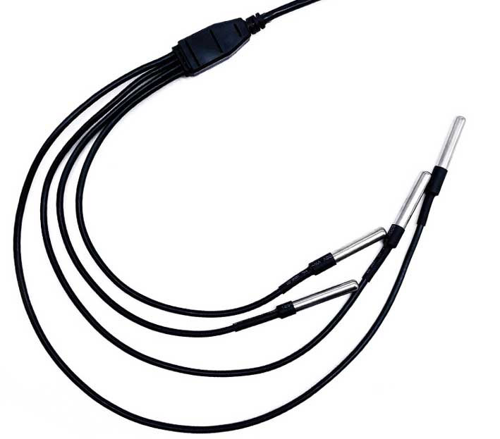
| DS18b20 digital temperature transmission sensor | ds18b20 refrigerator temperature control probe |
1. Introduction to DS18B20
(1) Unique single-wire interface method: When DS18B20 is connected to the microprocessor, only one port line is needed to achieve two-way communication between the microprocessor and DS18B20.
(2) No external components are required during use.
(3) It can be powered by data line, voltage range: +3.0~ +5.5 V.
(4) Temperature measurement range: -55 ~ +125 ℃. The inherent temperature measurement resolution is 0.5 ℃.
(5) Digital reading mode of 9~12 digits can be realized through programming.
(6) Users can set non-volatile alarm upper and lower limits.
(7) Support multi-point networking function, multiple DS18B20 can be connected in parallel on the only three lines to achieve multi-point temperature measurement.
(8) Negative voltage characteristics: When the polarity of the power supply is reversed, the thermometer will not burn due to heat, but it will not work properly.
Temperature measurement principle of DS18B20
The temperature measurement principle of DS18B20 is shown in Figure 2. The oscillation frequency of the low temperature coefficient crystal oscillator in the figure is very little affected by temperature [1]. It is used to generate a fixed frequency pulse signal and send it to the subtraction counter 1. The oscillation frequency of high temperature coefficient crystal oscillators changes significantly with temperature changes. The generated signal is used as the pulse input of subtraction counter 2. There are also counting gates implicit in the figure. When the counting gate is opened, the DS18B20 counts the clock pulses generated by the low temperature coefficient oscillator to complete the temperature measurement. The opening time of the counting gate is determined by a high temperature coefficient oscillator. Before each measurement, first put the base number corresponding to -55 ℃ into the subtraction counter 1 and the temperature register respectively. The down counter 1 and the temperature register are preset at a base value corresponding to -55°C. Subtraction counter 1 performs subtraction counting on the pulse signal generated by the low temperature coefficient crystal oscillator. When the preset value of subtraction counter 1 decreases to 0, the value of the temperature register will be increased by 1, and the preset value of subtraction counter 1 will be reloaded. Subtraction counter 1 restarts counting the pulse signal generated by the low temperature coefficient crystal oscillator, and this cycle continues until subtraction counter 2 counts to 0, and then stops accumulating the temperature register value. At this time, the value in the temperature register is the measured temperature. The slope accumulator in Figure 2 is used to compensate and correct the nonlinearity in the temperature measurement process, and its output is used to correct the preset value of the subtraction counter. As long as the counting gate is not closed, the above process is repeated until the temperature register value reaches the measured temperature value. This is the temperature measurement principle of DS18B20.
In addition, since the DS18B20 single-line communication function is completed in time sharing, it has a strict time slot concept, so the read and write timing is very important. Various operations of the system on DS18B20 must be performed according to the protocol. The operation protocol is: initialize DS18B20 (send reset pulse) → send ROM function command → send memory operation command → process data. The timing diagram for various operations is the same as that of the DS1820.
DS18B20 working process and timing
The low temperature coefficient oscillator inside the DS18B20 is an oscillator whose oscillation frequency changes very little with temperature, providing a stable frequency counting pulse for counter 1.
The high temperature coefficient oscillator is an oscillator whose oscillation frequency is very sensitive to temperature and provides counter 2 with a counting pulse whose frequency changes with temperature.
Initially, the temperature register is preset to -55°C. Whenever counter 1 counts down from the preset number to 0, the temperature value registered in the temperature register increases by 1°C. This process is repeated until counter 2 reaches 0 and then stops.
Initially, counter 1 is preset with a preset value corresponding to -55°C. In the future, the preset number of each cycle of counter 1 is provided by the slope accumulator. In order to compensate for the non-linearity of the oscillator temperature characteristics, the preset number provided by the slope accumulator also changes accordingly with the temperature. The preset number of counter 1 is the number of counts required to increase the temperature register value by 1°C at a given temperature.
The comparator inside the DS18B20 determines the least significant bit of the temperature register in a rounded quantization manner. After counter 2 stops counting, the comparator converts the remaining counting value in counter 1 into a temperature value and compares it with 0.25°C. If it is lower than 0.25℃, the lowest bit of the temperature register is set to 0. If it is higher than 0.25℃, the lowest bit is set to 1. If it is higher than 0.75℃, the lowest bit of the temperature register is carried and then set to 0. In this way, the value of the temperature register obtained after comparison is the final temperature value read, and the last bit represents 0.5°C. The maximum rounding quantization error is ±1/2LSB, which is 0.25°C.
The temperature value in the temperature register is expressed in a 9-bit data format, the highest bit is the sign bit, and the remaining 8 bits represent the temperature value in two's complement form. At the end of the temperature measurement, these 9-bit data are transferred to the first two bytes of the temporary storage memory, and the sign bit occupies the first byte. The 8-bit temperature data occupies the second byte.
DS18B20 uses unique temperature measurement technology when measuring temperature. The low temperature coefficient oscillator inside the DS18B20 can produce a stable frequency signal. Similarly, a high temperature coefficient oscillator converts the measured temperature into a frequency signal. When the counting gate is opened, DS18B20 counts, and the counting gate opening time is determined by the high temperature coefficient oscillator. There is also a slope accumulator inside the chip to compensate for frequency nonlinearity. The measurement results are stored in the temperature register. Under normal circumstances, the temperature value should be 9 bits, but because the sign bit is extended to the upper 8 bits, it is finally read out in 16-bit complement form.
The working process of DS18B20 generally follows the following protocol: initialization - ROM operation command - memory operation command - data processing
① Initialization
All processing on a single bus begins with an initialization sequence. The initialization sequence includes a reset pulse from the bus master, followed by a presence pulse from the slave device. The presence of the pulse lets the bus controller know that the DS1820 is on the bus and is ready to operate.
② ROM operation command
Once the bus master detects the presence of a slave device, it can issue one of the device ROM operation commands. All ROM operation commands are 8 bits long. The list of these commands is as follows:
Read ROM (read ROM)[33h]
This command allows the bus master to read the DS18B20's 8-bit product family code, unique 48-bit serial number, and 8-bit CRC. This command can only be used when there is only one DS18B20 on the bus. If there is more than one slave device on the bus, data collisions will occur when all slaves attempt to transmit at the same time (an open drain will produce a wired AND result).
Match ROM(match ROM)[55h]
This command is followed by a 64-bit ROM data sequence, allowing the bus master to address a specific DS18B20 on the multidrop bus. Only the DS18B20 that strictly matches the 64-bit ROM sequence can respond to subsequent memory operation commands. All slaves that do not match the 64-bit ROM sequence will wait for a reset pulse. This command can be used with single or multiple devices on the bus.
Skip ROM(skip ROM)[CCh]
In single-point bus systems, this command saves time by allowing the bus master to access memory operations without providing 64-bit ROM encoding. If there is more than one slave device on the bus and a read command is issued after the Skip ROM command, data conflicts will occur on the bus due to multiple slave devices sending data at the same time.
Search ROM(Search ROM)[F0h]
When the system starts working, the bus master may not know the number of devices on the single-wire bus or its 64-bit ROM code. The Search ROM command allows the bus controller to identify the 64-bit codes of all slaves on the bus by process of elimination.
Alarm Search (alarm search) [ECh]
The flow of this command is the same as the search ROM command. However, the DS18B20 will only respond to this command if an alarm occurred during the most recent temperature measurement. The alarm condition is defined as the temperature being higher than TH or lower than TL. As soon as the DS18B20 is powered on, the alarm condition remains set until another temperature measurement shows a non-alarm value or the TH or TL setting is changed so that the measured value is once again within the allowed range. The trigger value stored in EEPROM is used for alarms.
③ Memory operation command
Write Scratchpad (write scratchpad) [4Eh]
This command writes data to the temporary register of DS18B20, starting at address 2. The next two bytes written will be stored in the scratchpad at address locations 2 and 3. A reset command can be issued at any time to abort writing.
Read Scratchpad [BEh]
This command reads the contents of the scratchpad. Reading will start from byte 0 and continue until the 9th (byte 8, CRC) byte is read. If it does not want to read all bytes, the controller can issue a reset command at any time to abort the read.
Copy Scratchpad (copy scratchpad) [48h]
This command copies the contents of the temporary register to the E2 memory of DS18B20, that is, stores the temperature alarm trigger byte in non-volatile memory. If the bus controller issues a read time gap after this command and the DS18B20 is busy copying the scratchpad to E2 memory, the DS18B20 will output a "0". If the copy is completed, DS18B20 will output "1". If parasitic power is used, the bus controller must initiate a strong pull-up immediately after this command is issued and maintain it for at least 10ms.
Convert T (temperature conversion) [44h]
This command initiates a temperature conversion without requiring additional data. The temperature conversion command is executed, and then the DS18B20 remains in a wait state. If the bus controller issues a read time gap after this command and the DS18B20 is busy doing time conversion, the DS18B20 will output "0" on the bus and "1" if the temperature conversion is completed. If parasitic power is used, the bus controller must initiate a strong pull-up immediately after issuing this command and maintain it for 500ms.
Recall E2 (Recall E2) [B8h]
This command resets the value of the temperature trigger stored in E2 to the temporary memory. This recall operation also occurs automatically when the DS18B20 is powered on, so as soon as the device is powered on, there is valid data in the temporary memory. After this command is issued, for the first read data time slice issued, the device will output a temperature conversion busy flag: "0" = busy, "1" = ready.
Read Power Supply [B4h]
For the time slice of the first read data issued after this command is sent to the DS18B20, the device will give a signal of its power mode: "0" = powered by a parasitic power supply, "1" = powered by an external power supply.
④ Process data
The high-speed scratchpad memory of DS18B20 consists of 9 bytes, and its allocation is shown in Figure 3. When the temperature conversion command is issued, the converted temperature value is stored in the 0th and 1st bytes of the cache memory in two-byte complement form. The microcontroller can read the data through the single-wire interface, with the low bit in front and the high bit in the back.
Figure 3 Cache memory allocation diagram
DS18B20 Temperature Data Sheet
The above table is the 12-bit data obtained after temperature acquisition and conversion by DS18B20. Stored in two 8-bit RAMs of DS18B20, the first 5 bits in binary are sign bits. If the measured temperature is greater than or equal to 0, these 5 bits are 0. Just multiply the measured value by 0.0625 to get the actual temperature. If the temperature is less than 0, these 5 bits are 1, and the measured value needs to be inverted, plus 1, and then multiplied by 0.0625 to get the actual temperature.
Example of temperature conversion calculation method:
For example, when DS18B20 collects the actual temperature of +125°C, the output is 07D0H, then:
Actual temperature=07D0H╳0.0625=2000╳0.0625=1250C.
For example, when DS18B20 collects the actual temperature of -55°C and outputs FC90H, the 11 data bits should be inverted and added by 1 to get 370H (the sign bit remains unchanged and is not included in the calculation), then:
Actual temperature=370H╳0.0625=880╳0.0625=550C.


