51/2.3 Microcontroller Controls DS18B20 Temperature Sensor Module
Through the previous example of LCD1602 digital temperature sensing, I believe that I have a basic understanding of the control and delay of the IO port. Here is another example of a temperature sensor, which also only requires IO port operation and delay. First, let’s give an introduction to the DS18B20 temperature sensor. Since it is a temperature sensor, there must be a sensor that senses temperature. This sensor converts the temperature around it directly into a number and stores it in the scratchpad memory. We don’t need to understand this process of sensing temperature and converting it into a digital signal. What we have to do is read the contents of the memory and some other configurations. The schematic diagram is as follows:
Figure 1, DS18B20 temperature sensor overview
There is a temperature sensor in DS18B20 (as shown in the picture above), which can sense the ambient temperature and directly convert the temperature result into a digital signal for storage. We don't need to worry about the process of converting the temperature signal into a digital signal. So where does the digital signal exist? There is a memory called ScratchPad in DS18B20, with a total of 9 bytes (Byte0-Byte8), and the digital signals are stored in Byte0_LSM and Byte1_MSB. Among them, Byte0 is the low bit and Byte1 is the high bit. In fact, our purpose is to read the digital signals stored in Byte0 and Byte1. It can be seen that although the name is temperature sensor module, we do not need to care about the sensing process at all in our thinking process. This is actually the same as the LCD1602 mentioned earlier. All we have to do is read or write. This is what modules are for, we can treat them as black boxes. According to its rules, you only need to know what you input into it and what it will produce. You don’t need to pay attention to the intermediate process. We combine Byte0_LSM and Byte1_MSB into a 16-bit digital signal, with Byte0_LSB as the low bit and Byte1_MSB as the high bit, and name it "T-16bit", as shown in the figure above. So how to convert this "T-16bit" digital signal into temperature? As can be seen from the figure, bit11-bit15 are S, indicating the positive and negative temperature. If S=0, then the temperature is positive, if S=1 then the temperature is negative. For the following bit10-bit0, each increase in the value by one means that the temperature increases by 0.0625°C. For example: If the LSB reads 1100 0011 and the MSB reads 0000 0110, then the combination of LSB and MSB "T-16bit" is 0000 0110 1100 0011. The high 5 bits are 0, indicating that the temperature is positive. The remaining 11 bits bit10-bit0 (110 1100 0011=1731), put 1731×0.0625=108.1875, then the measured temperature is +108.1875°C. If the LSB and MSB combined "T-16bit" is 1111 1110 1100 0011, then the measured temperature is -108.1875°C. In "T-16bit", we can also understand it this way. Every increment of bit0 by 1 means 20×0.0625°C, and every change of bit1 by 1 means 21×0.0625°C. By analogy, every 1 change in bit4 is 24×0.0625°C=1°C.
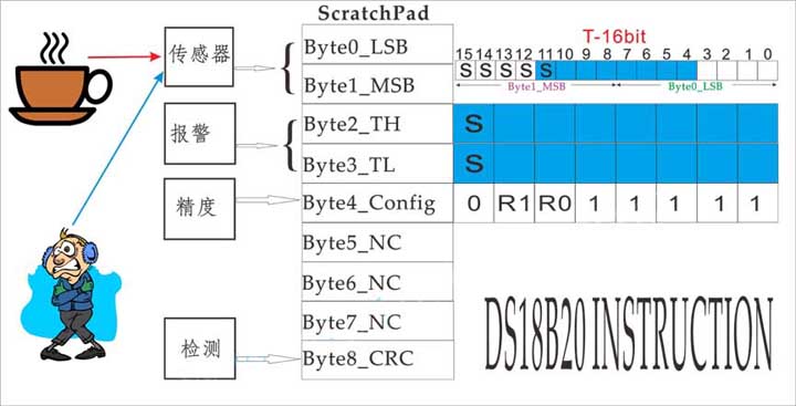 Then there are the alarm functions of Byte2_TH and Byte3_TL. In the figure, Byte2_TH represents the maximum temperature set, and Byte3_TL represents the minimum temperature set. Similarly, S represents the positive and negative temperature. If S=0, it means positive; if S=1, then the temperature is negative. Byte2_TH and Byte3_TL represent the range of the set temperature. Note that Byte2_TH and Byte3_TL here correspond to bit11 to bit4 in "T-16bit", as shown in the blue part in the figure. As mentioned before, in "T-16bit", every change of 1 in bit4 is 1°C, so every change of 1 in the lowest bit in Byte2_TH and Byte3_TL means that the temperature changes by 1°C. For example, Byte2_TH is set to 01111001 (121 in decimal), and the first bit is 0, which means +121°C. Byte3_TL is 01001001 (73 in decimal), and the first bit is 0, which means +73°C. Therefore, the temperature setting range is: 73-121°C. When the temperature in "T-16bit" is higher than/equal to +121°C, or lower than/equal to 73°C, the alarm will be triggered.
The next step is to set the accuracy of temperature collection, as shown in Byte4_Config in the figure. Bit5 and bit6 are R0 and R1 respectively, and the other bits are fixed. R0 and R1 can be 0 or 1 respectively, so they can be combined into 4 situations, 00/01/10/11, corresponding to different precisions, as shown in the following table:
Byte5-Byte7 are not given, Byte8 is CRC used for communication error detection. Let's leave it alone for now and let's consider the easy part first
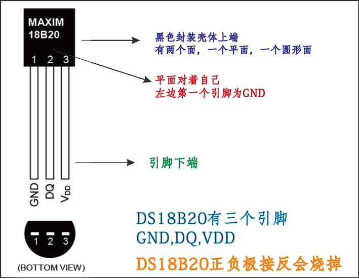
Through the above explanation, I believe I have a preliminary understanding of DS18B20. Now let's talk about how it communicates with the microcontroller. DS18B20 has three pins in total, two power pins (positive and negative power supply), and one data pin DQ. Its structure diagram is shown below. The black shell faces up, the pins face down, and the flat surface faces you. The first pin on the left is GND. If the positive and negative poles of DS18B20 are connected reversely, it may burn.
It can be seen that the communication between the microcontroller and DS18B20 can only rely on this line. In addition, multiple DS18B20 can be connected to this line at the same time. So how does the microcontroller accurately communicate with multiple DS18B20s through this single line? The microcontroller does not know whether there is a DS18B20 on the DQ line, or there are multiple ones, or there is one but it is broken. The same way as people communicate, when you don't know what's going on in the room, you will say hello first and ask if anyone is there. Likewise, the same goes for microcontrollers. Let’s do some initialization first, say hello, and see if there is 18B20 on the DQ line. How to say hello is the same as the LCD1602 mentioned above, of course according to the rules of DS18B20. The microcontroller must first pull DQ low for at least 480μS, and then release DQ. After about 15-60μS, if there is a DS18B20 on the line and working normally, then the DS18B20 will pull DQ low and maintain it for 60-240μS. The microcontroller checks this signal to determine whether there is a DS18B20 on the line that can work normally. There are as many DS18B20s as there are signals. This is the rule of DS18B20, as follows:
Can I communicate with DS18B20 after initialization? If there are multiple DS18B20s online, which one do you want to communicate with? Therefore, you must first identify the target before communicating. Here we take the simplest DS18B20. Once you understand one, you will naturally be able to control multiple DS18B20s. Let’s take a look at how to write the initialization code,
 step1: First, DQ is pulled low and maintained at least 480Us. Here we take 500Us for insurance
step2: Release the bus (DQ=1). After waiting for about 15-60Us, DS18B20 will pull DQ low. So should I choose 15Us or 60Us here?
step3: At this time, DS18B20 pulls the DQ low signal (L_DQ) for 60-240Us. So should I choose 60Us or 240Us?
Note that our purpose here is to detect whether DS18B20 pulls down the DQ signal (L_DQ). So in step 2, after releasing the bus (DQ=1), how long do we need to delay (Tdelay) to read the signal whether DQ is equal to 0?
Let's make an extreme assumption, the minimum and maximum values
(1) In step 2, the microcontroller releases the bus (DQ=1), and after waiting for 15Us (minimum value), DS18B20 pulls DQ low. In step 3, DQ pulled low for 60Us (minimum value)
In this case, if Tdelay>75Us, you cannot detect the L_DQ signal. Therefore Tdelay should be less than 75Us.
(2) In step 2, the microcontroller releases the bus (DQ=1), and after waiting for 60Us (maximum value), DS18B20 pulls DQ low. In step 3, the DQ pull down lasted for 60/240Us (two situations)
In this case, if Tdelay<60Us, you cannot detect the L_DQ signal. For example, if you set Tdelay=50Us and then read DQ, DQ is still 1. Why? Because after 60Us
DS18B20 only pulls DQ low. Therefore Tdelay>60Us.
To sum up, the insurance time is: 75Us>Tdelay>60Us, and the code is as follows:
void ds18b20_init(void)
{
DQ=0;//pull the bus low
delayUs(240); //Delay 526Us
DQ=1;//Release the bus
delayUs(28);//delay 66Us (between 60-75Us)
if(DQ==0)
{
LED1=0;//(Set an LED, if DQ=0 is detected, light LED1)
}
else
{
LED2=0;
}
delayUs(240);//Please note that after reading DQ, continue to delay 480Us
}
The ID signal of DS18B20 is in ROM, so we can skip reading ROM here (Skip ROM[CCh]).
Next comes the part of communicating with DS18B20. DS18B20 is passive when powered on, which means it is passive and will not work without instructions. Therefore, the first instruction given by the microcontroller to DS18B20 is to let it start measuring temperature (Convert T [44h]). What does DS18B20 do when it receives this command? Here we go back to Figure 1 we talked about earlier. DS18B20 begins to sense the surrounding temperature and converts the temperature into digital signals and stores them in Byte0 and Byte1 in ScratchPad. From here we know that we only need one command, Convert T, to let DS18B20 start temperature measurement and storage. We don't care how this process happens. From here we see that there is actually no essential difference between the control DS18B20 module and the LCD1602 module. All we have to do is read the rules. These rules are sourced from their chip manuals. To put it simply, it is to read and understand the chip manual. This point is actually ignored by many beginners, who are unwilling or not accustomed to checking the chip manual. It takes a certain amount of time for DS18B20 to convert the temperature signal into a digital signal, so before issuing the next command, we need to check whether DS18B20 is still working. If you want to simplify it, use a delay. After the conversion is completed, DS18B20 is in a passive state again, and this conversion process is not continuous. Therefore, if you want it to be converted again, you must issue the Convert T command again.
So how to issue instructions? This involves the 'DS18B20 writing' part. Refer to the data sheet and find the ‘Write Timing
First, let’s look at how the microcontroller writes 0 and 1 to DS18B20.
(1) Write 0: DQ is pulled low and maintained at least 60Us. At about 15-60Us, DS18B20 starts accepting data
(2) Write 1: pull DQ low, delay 2Us, and then release DQ. At this time, the pull-up resistor will pull DQ high, with a delay of at least 60Us. At 15-60Us, DS18B20 starts to receive data
So the code to write the instruction is as follows
void ds18b20_com(unsigned char mycom)
{
unsigned char temp;
unsigned char i;
for (i=0;i<8;i++)
{
temp=mycom & 0x01;
if (temp==1)
{
DQ=0;
_nop_();
_nop_();
DQ=1;
delayUs(35);
}
else
{
DQ=0;
delayUs(35);
DQ=1;
}
mycom>>=1;
}
}
So, if you want to issue the command ds18b20_com(0xcch)//skip rom, DS18B20 will know to skip reading the ROM. If you want to send the command Convert T, ds18b20_com (0x44h), DS18B20 starts temperature conversion and stores the first two bytes in ScratchPad.
When the conversion is completed, the data is stored in Byte0 and Byte1, and the next task is to read Byte0 and Byte1. What needs to be noted here is that before each instruction sent by the microcontroller, it must be: initialization->ROM instruction->function instruction. This is specified in the chip manual. Therefore, before reading Byte0 and Byte1, you need to initialize it again, Skip ROM ([CCh]), and you can read Byte0 and Byte1. Then merge Byte0 and Byte1, and then convert them into temperature.
Now let's see how to read DS18B20. Also check the chip manual to find the read timing diagram.
DS18B20 wants to send data to the microcontroller. So how does DS18B20 know when the microcontroller starts to ask for data? There is also a rule here. When the microcontroller pulls DQ low, it delays 1Us and then releases DQ. At this time, DS18B20 knows, oh, the microcontroller starts to ask for data. If DS18B20 wants to write 0 at this time, pull DQ low. On the contrary, if it wants to write 1, keep DQ high. The read data information is sent from the microcontroller, DS18B20 gives the data, and the microcontroller collects the data. This process needs to be completed in 15Us, and then it needs to be delayed by 45Us. To be safe, we take 65Us here. There must be at least 1Us interval between two reads. Therefore, it is easy to get the code for the microcontroller to read DS18B20:
unsigned int ds18b20_read(void)
{
unsigned char temp1=0;
unsigned int temp2=0;
unsigned int temp=0;
unsigned char i;
for (i=0;i<8;i++)
{
temp1>>=1;
DQ=0;
_nop_();
_nop_();
DQ=1;
if(DQ==1)
temp1 |=0x80;
delayUs(35);
}
for (i=0;i<8;i++)
{
temp2>>=1;
DQ=0;
_nop_();
_nop_();
DQ=1;
if(DQ==1)
temp2 |=0x80;
delayUs(35);
}
temp2 <<=8;
temp=temp1+temp2;
return temp;
}
It can be seen from the two examples of LCD1602 and DS18B20 that the control of these two modules actually only uses the pin control and delay program of the microcontroller. The focus and difficulty lies in understanding the control rules of each module. In fact, these can be found by carefully reading the corresponding chip manual. The control and delay parts of the microcontroller pins are no different from the operation of the LED. No wonder some people say that if you truly understand the process of operating LEDs, you will have learned half of the microcontroller. Later we will repeatedly use LED as an example to explain other related content of microcontrollers.
 |
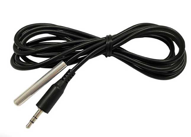 |
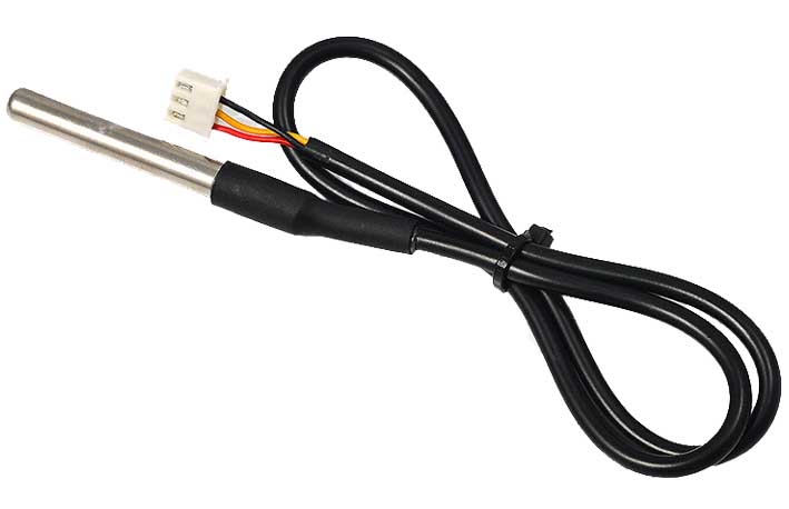
| DS18B20 Temperature Sensor with 3 Cables | DS18B20 temperature sensor conversion connector |
Figure 1, DS18B20 temperature sensor overview
There is a temperature sensor in DS18B20 (as shown in the picture above), which can sense the ambient temperature and directly convert the temperature result into a digital signal for storage. We don't need to worry about the process of converting the temperature signal into a digital signal. So where does the digital signal exist? There is a memory called ScratchPad in DS18B20, with a total of 9 bytes (Byte0-Byte8), and the digital signals are stored in Byte0_LSM and Byte1_MSB. Among them, Byte0 is the low bit and Byte1 is the high bit. In fact, our purpose is to read the digital signals stored in Byte0 and Byte1. It can be seen that although the name is temperature sensor module, we do not need to care about the sensing process at all in our thinking process. This is actually the same as the LCD1602 mentioned earlier. All we have to do is read or write. This is what modules are for, we can treat them as black boxes. According to its rules, you only need to know what you input into it and what it will produce. You don’t need to pay attention to the intermediate process. We combine Byte0_LSM and Byte1_MSB into a 16-bit digital signal, with Byte0_LSB as the low bit and Byte1_MSB as the high bit, and name it "T-16bit", as shown in the figure above. So how to convert this "T-16bit" digital signal into temperature? As can be seen from the figure, bit11-bit15 are S, indicating the positive and negative temperature. If S=0, then the temperature is positive, if S=1 then the temperature is negative. For the following bit10-bit0, each increase in the value by one means that the temperature increases by 0.0625°C. For example: If the LSB reads 1100 0011 and the MSB reads 0000 0110, then the combination of LSB and MSB "T-16bit" is 0000 0110 1100 0011. The high 5 bits are 0, indicating that the temperature is positive. The remaining 11 bits bit10-bit0 (110 1100 0011=1731), put 1731×0.0625=108.1875, then the measured temperature is +108.1875°C. If the LSB and MSB combined "T-16bit" is 1111 1110 1100 0011, then the measured temperature is -108.1875°C. In "T-16bit", we can also understand it this way. Every increment of bit0 by 1 means 20×0.0625°C, and every change of bit1 by 1 means 21×0.0625°C. By analogy, every 1 change in bit4 is 24×0.0625°C=1°C.
The next step is to set the accuracy of temperature collection, as shown in Byte4_Config in the figure. Bit5 and bit6 are R0 and R1 respectively, and the other bits are fixed. R0 and R1 can be 0 or 1 respectively, so they can be combined into 4 situations, 00/01/10/11, corresponding to different precisions, as shown in the following table:
Byte5-Byte7 are not given, Byte8 is CRC used for communication error detection. Let's leave it alone for now and let's consider the easy part first
Through the above explanation, I believe I have a preliminary understanding of DS18B20. Now let's talk about how it communicates with the microcontroller. DS18B20 has three pins in total, two power pins (positive and negative power supply), and one data pin DQ. Its structure diagram is shown below. The black shell faces up, the pins face down, and the flat surface faces you. The first pin on the left is GND. If the positive and negative poles of DS18B20 are connected reversely, it may burn.
It can be seen that the communication between the microcontroller and DS18B20 can only rely on this line. In addition, multiple DS18B20 can be connected to this line at the same time. So how does the microcontroller accurately communicate with multiple DS18B20s through this single line? The microcontroller does not know whether there is a DS18B20 on the DQ line, or there are multiple ones, or there is one but it is broken. The same way as people communicate, when you don't know what's going on in the room, you will say hello first and ask if anyone is there. Likewise, the same goes for microcontrollers. Let’s do some initialization first, say hello, and see if there is 18B20 on the DQ line. How to say hello is the same as the LCD1602 mentioned above, of course according to the rules of DS18B20. The microcontroller must first pull DQ low for at least 480μS, and then release DQ. After about 15-60μS, if there is a DS18B20 on the line and working normally, then the DS18B20 will pull DQ low and maintain it for 60-240μS. The microcontroller checks this signal to determine whether there is a DS18B20 on the line that can work normally. There are as many DS18B20s as there are signals. This is the rule of DS18B20, as follows:
Can I communicate with DS18B20 after initialization? If there are multiple DS18B20s online, which one do you want to communicate with? Therefore, you must first identify the target before communicating. Here we take the simplest DS18B20. Once you understand one, you will naturally be able to control multiple DS18B20s. Let’s take a look at how to write the initialization code,
step2: Release the bus (DQ=1). After waiting for about 15-60Us, DS18B20 will pull DQ low. So should I choose 15Us or 60Us here?
step3: At this time, DS18B20 pulls the DQ low signal (L_DQ) for 60-240Us. So should I choose 60Us or 240Us?
Note that our purpose here is to detect whether DS18B20 pulls down the DQ signal (L_DQ). So in step 2, after releasing the bus (DQ=1), how long do we need to delay (Tdelay) to read the signal whether DQ is equal to 0?
Let's make an extreme assumption, the minimum and maximum values
(1) In step 2, the microcontroller releases the bus (DQ=1), and after waiting for 15Us (minimum value), DS18B20 pulls DQ low. In step 3, DQ pulled low for 60Us (minimum value)
In this case, if Tdelay>75Us, you cannot detect the L_DQ signal. Therefore Tdelay should be less than 75Us.
(2) In step 2, the microcontroller releases the bus (DQ=1), and after waiting for 60Us (maximum value), DS18B20 pulls DQ low. In step 3, the DQ pull down lasted for 60/240Us (two situations)
In this case, if Tdelay<60Us, you cannot detect the L_DQ signal. For example, if you set Tdelay=50Us and then read DQ, DQ is still 1. Why? Because after 60Us
DS18B20 only pulls DQ low. Therefore Tdelay>60Us.
To sum up, the insurance time is: 75Us>Tdelay>60Us, and the code is as follows:
void ds18b20_init(void)
{
DQ=0;//pull the bus low
delayUs(240); //Delay 526Us
DQ=1;//Release the bus
delayUs(28);//delay 66Us (between 60-75Us)
if(DQ==0)
{
LED1=0;//(Set an LED, if DQ=0 is detected, light LED1)
}
else
{
LED2=0;
}
delayUs(240);//Please note that after reading DQ, continue to delay 480Us
}
The ID signal of DS18B20 is in ROM, so we can skip reading ROM here (Skip ROM[CCh]).
Next comes the part of communicating with DS18B20. DS18B20 is passive when powered on, which means it is passive and will not work without instructions. Therefore, the first instruction given by the microcontroller to DS18B20 is to let it start measuring temperature (Convert T [44h]). What does DS18B20 do when it receives this command? Here we go back to Figure 1 we talked about earlier. DS18B20 begins to sense the surrounding temperature and converts the temperature into digital signals and stores them in Byte0 and Byte1 in ScratchPad. From here we know that we only need one command, Convert T, to let DS18B20 start temperature measurement and storage. We don't care how this process happens. From here we see that there is actually no essential difference between the control DS18B20 module and the LCD1602 module. All we have to do is read the rules. These rules are sourced from their chip manuals. To put it simply, it is to read and understand the chip manual. This point is actually ignored by many beginners, who are unwilling or not accustomed to checking the chip manual. It takes a certain amount of time for DS18B20 to convert the temperature signal into a digital signal, so before issuing the next command, we need to check whether DS18B20 is still working. If you want to simplify it, use a delay. After the conversion is completed, DS18B20 is in a passive state again, and this conversion process is not continuous. Therefore, if you want it to be converted again, you must issue the Convert T command again.
So how to issue instructions? This involves the 'DS18B20 writing' part. Refer to the data sheet and find the ‘Write Timing
First, let’s look at how the microcontroller writes 0 and 1 to DS18B20.
(1) Write 0: DQ is pulled low and maintained at least 60Us. At about 15-60Us, DS18B20 starts accepting data
(2) Write 1: pull DQ low, delay 2Us, and then release DQ. At this time, the pull-up resistor will pull DQ high, with a delay of at least 60Us. At 15-60Us, DS18B20 starts to receive data
So the code to write the instruction is as follows
void ds18b20_com(unsigned char mycom)
{
unsigned char temp;
unsigned char i;
for (i=0;i<8;i++)
{
temp=mycom & 0x01;
if (temp==1)
{
DQ=0;
_nop_();
_nop_();
DQ=1;
delayUs(35);
}
else
{
DQ=0;
delayUs(35);
DQ=1;
}
mycom>>=1;
}
}
So, if you want to issue the command ds18b20_com(0xcch)//skip rom, DS18B20 will know to skip reading the ROM. If you want to send the command Convert T, ds18b20_com (0x44h), DS18B20 starts temperature conversion and stores the first two bytes in ScratchPad.
When the conversion is completed, the data is stored in Byte0 and Byte1, and the next task is to read Byte0 and Byte1. What needs to be noted here is that before each instruction sent by the microcontroller, it must be: initialization->ROM instruction->function instruction. This is specified in the chip manual. Therefore, before reading Byte0 and Byte1, you need to initialize it again, Skip ROM ([CCh]), and you can read Byte0 and Byte1. Then merge Byte0 and Byte1, and then convert them into temperature.
Now let's see how to read DS18B20. Also check the chip manual to find the read timing diagram.
DS18B20 wants to send data to the microcontroller. So how does DS18B20 know when the microcontroller starts to ask for data? There is also a rule here. When the microcontroller pulls DQ low, it delays 1Us and then releases DQ. At this time, DS18B20 knows, oh, the microcontroller starts to ask for data. If DS18B20 wants to write 0 at this time, pull DQ low. On the contrary, if it wants to write 1, keep DQ high. The read data information is sent from the microcontroller, DS18B20 gives the data, and the microcontroller collects the data. This process needs to be completed in 15Us, and then it needs to be delayed by 45Us. To be safe, we take 65Us here. There must be at least 1Us interval between two reads. Therefore, it is easy to get the code for the microcontroller to read DS18B20:
unsigned int ds18b20_read(void)
{
unsigned char temp1=0;
unsigned int temp2=0;
unsigned int temp=0;
unsigned char i;
for (i=0;i<8;i++)
{
temp1>>=1;
DQ=0;
_nop_();
_nop_();
DQ=1;
if(DQ==1)
temp1 |=0x80;
delayUs(35);
}
for (i=0;i<8;i++)
{
temp2>>=1;
DQ=0;
_nop_();
_nop_();
DQ=1;
if(DQ==1)
temp2 |=0x80;
delayUs(35);
}
temp2 <<=8;
temp=temp1+temp2;
return temp;
}
It can be seen from the two examples of LCD1602 and DS18B20 that the control of these two modules actually only uses the pin control and delay program of the microcontroller. The focus and difficulty lies in understanding the control rules of each module. In fact, these can be found by carefully reading the corresponding chip manual. The control and delay parts of the microcontroller pins are no different from the operation of the LED. No wonder some people say that if you truly understand the process of operating LEDs, you will have learned half of the microcontroller. Later we will repeatedly use LED as an example to explain other related content of microcontrollers.


