Measurement method of RTD Temperature Sensor
Platinum resistance temperature sensor (Pt100 and Pt1000), as a high-precision temperature sensor, is widely used in meteorology, automobiles, aviation, industrial automation measurement and various experimental instrumentation and other fields. The temperature measurement principle of the platinum resistance temperature sensor is that the resistance value of metal platinum (PT) changes as the ambient temperature changes, and there is a definite functional relationship between the resistance value and the temperature value.
1. Three lead methods of platinum resistance temperature sensor
According to the different lead methods of temperature sensors, platinum resistors are divided into three types: two-wire system, three-wire system and four-wire system. The three lead methods have their own characteristics: the two-wire lead method has simple leads, but the problem is that the measurement error is large, and the wire resistance error is inevitably introduced during the measurement. It is only suitable for occasions where the measurement accuracy is not high.
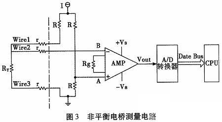
The three-wire lead method uses two leads on one end and one lead on the other end. In industry, the three-wire connection method is generally adopted. The three wires drawn out in the three-wire lead method have the same cross-sectional area and length. Usually the three-wire resistance is measured using the unbalanced bridge method, which can eliminate the influence of the inner lead resistance during measurement, and the measurement accuracy is higher than that of the two-wire system.
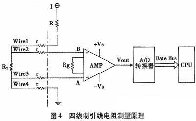
In the four-wire lead method, two wires are power supply wires and the other two are signal wires. The power supply and signal work separately, and this method can effectively remove line resistance. If the resistance of the resistor to be measured is equal to or even much smaller than the wire resistance, only the four-wire measurement method can be used. This method has higher measurement accuracy, but this method requires the sensor to generate 4 leads, which will increase the cost and weight of the entire test system during long-distance transmission, and cannot meet the requirements of some special industries. Mainly used for high-precision temperature detection.
 2. Two-wire platinum resistance measurement circuit
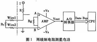
In a platinum resistance temperature sensor measurement system, the platinum resistance value is usually calculated using the output voltage Vo when the whist bridge is unbalanced. The acquisition circuit of the two-wire platinum resistor in this system is shown in Figure 1.
Measurement methods and applications of platinum resistance temperature sensors:
I is the constant voltage source, R is the current limiting resistor, the resistance to be measured is Rt, and the line resistance is r. The test circuit is shown in Figure 1. Calculated according to Ohm’s law:
Measurement methods and applications of platinum resistance temperature sensors:
 In the above formula, RT: the resistance value of the measured platinum resistance sensor; r: the sensor lead resistance value; k: the operational amplifier linear amplification system (usually set by the gain resistor Rg); VOUT: the operational amplifier output voltage value.
It can be seen from equation (2) that using two-wire transmission will bring a measurement error of 2r. The transmission line used in the measurement system has a resistance of approximately 0.061 Ω per meter, and 2r is 0.122 Ω. Assuming that the lead between the measurement resistance and the measurement circuit in the system is 50 m long, the error caused by the lead resistance will reach 3.05 Ω. That is, the temperature measurement error will reach 7.6°C (the resistance change of the platinum resistor in the system is about 0.398 Ω for every 1°C change).
It can be seen that when the distance between the measurement system and the sensor is long, the line resistance r has a great influence on the platinum resistance collection accuracy. Therefore, the two-wire platinum resistor is only suitable for occasions where the lead distance is relatively close and the measurement accuracy is average.
3. Three-wire resistance measurement circuit
3.1 Wheatstone Bridge
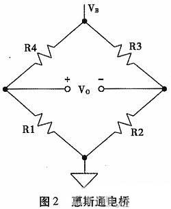
When the resistor bridge reaches balance, it can be seen from equation (3) that no matter whether the excitation source is current type or power type, and regardless of the size of the excitation source, the output of V0 is zero. Therefore, if R2/R3 is a fixed coefficient K, then when R1=K×R4, the bridge will reach balance, that is: Vo=0.
This balance value measurement method is often used in feedback control systems. Even very small changes in the resistance on the bridge arm will be reflected in changes in the output voltage. By monitoring whether the bridge is balanced, changes in the sensor monitoring objects (force, temperature, etc.) can be monitored in real time. The output voltage VO of the bridge is used as the feedback signal of the actuator to monitor the execution deviation in real time and continuously correct the execution instructions. Commonly used in the fields of torque measurement and electrothermal regulation controllers.
Normally, we think that the excitation source VR is a fixed value. It can be seen from equation (1) that the bridge output voltage VO has a linear proportional relationship with the excitation power supply VR. Therefore the measurement system can never be more accurate than the excitation power supply.
 3.2 Three-wire leaded unbalanced bridge measurement circuit
According to the whist bridge theory, when the bridge is working, one of the four bridge arms of the bridge changes, and R1 becomes R’=R1+△r. Then the balance of the whist bridge will be broken, that is, in Figure 2, there is a certain potential difference UL between A and B, then the bridge is called an unbalanced bridge, that is, VO=UL≠0.
Using the unbalanced bridge principle, various resistance sensors RT are connected to the bridge circuit. The unbalanced voltage of the bridge can reflect small changes in the bridge arm resistance. Therefore, changes in external physical quantities (temperature, pressure, etc.) can be detected. R is the precision bridge arm resistance selected by the measurement system, and RT is the measured resistance.
The two input terminals are connected to an operational amplifier with high input impedance, so that the voltage drop caused by the bias current on the line resistor will be minimized, which will minimize the leakage current. According to Kirchhoff’s current and voltage law:
It can be seen from formula (4) that in this measurement system, when RT>R, because the output voltage VOUT of the bridge arm is negative, it is necessary to ensure that the output VOUT is always positive. Then the bridge arm resistance value R of the measurement system should be greater than the upper limit resistance value of the measured resistance RT. Taking PT1000 as an example, its resistance value is 1 000 Ω at 0°C, and its effective resistance change range is 803 Ω ~ 2 120 Ω (that is, the temperature change range is -50°C ~ 300°C). Then the bridge arm resistance R should be selected to be greater than the upper limit of the change of its platinum resistance value (2120 Ω). In this example, the bridge arm resistance R is selected as 2700 Ω, which fully meets the measurement requirements and will not cause overflow.
Under the condition that the excitation current source is a typical value of 1 mA, the variation range of VAB at this time is 153 ~ 575mV, and the AMP is a high-precision operational amplifier AD620 from TI. AD620 uses a differential amplifier to convert the voltage difference of the bridge arm output into a single-ended voltage and amplify it. The offset voltage of its differential amplifier is very small. Eliminating the offset means that the tiny differential signal at the output is amplified but the offset voltage is not amplified. The gain resistor is a high-precision resistor with a resistance value of 5 kΩ, and the gain of the operational amplifier is k=10.88. It can be known from the calculation of formula (4) that the effective output voltage range of VOUT is 1.667~6.259 V.
3.2.1 Collecting results when the sensor is abnormal
In platinum resistance temperature measurement systems, the working environment of platinum resistance sensors is usually harsh. The lead wire from the sensor lead end to the measurement system is usually more than ten meters long. It is also very important to protect the leads during design to avoid disconnection and mutual short circuits. In some special fields (such as aviation industry, oil exploration), the system requires that the measurement system should be able to actively identify when similar faults occur, and the system is required to have alarm capabilities.
3.2.1.1 In case of sensor open circuit
Sensor is open circuit. The test system can be divided into the following situations for analysis, as shown in Table 1.
It can be seen from Table 1 above that when the sensor has an open circuit fault, the output voltage of the operational amplifier VOUT=13.6 V or VOUT=-12.7 V, that is, under the open circuit condition of the sensor, the operational amplifier enters a saturated state. Under normal working conditions of the sensor, the output voltage VOUT of the operational amplifier is within the normal amplification area.
According to the different lead methods of temperature sensors, platinum resistors are divided into three types: two-wire system, three-wire system and four-wire system. The three lead methods have their own characteristics: the two-wire lead method has simple leads, but the problem is that the measurement error is large, and the wire resistance error is inevitably introduced during the measurement. It is only suitable for occasions where the measurement accuracy is not high.
The three-wire lead method uses two leads on one end and one lead on the other end. In industry, the three-wire connection method is generally adopted. The three wires drawn out in the three-wire lead method have the same cross-sectional area and length. Usually the three-wire resistance is measured using the unbalanced bridge method, which can eliminate the influence of the inner lead resistance during measurement, and the measurement accuracy is higher than that of the two-wire system.
In the four-wire lead method, two wires are power supply wires and the other two are signal wires. The power supply and signal work separately, and this method can effectively remove line resistance. If the resistance of the resistor to be measured is equal to or even much smaller than the wire resistance, only the four-wire measurement method can be used. This method has higher measurement accuracy, but this method requires the sensor to generate 4 leads, which will increase the cost and weight of the entire test system during long-distance transmission, and cannot meet the requirements of some special industries. Mainly used for high-precision temperature detection.
In a platinum resistance temperature sensor measurement system, the platinum resistance value is usually calculated using the output voltage Vo when the whist bridge is unbalanced. The acquisition circuit of the two-wire platinum resistor in this system is shown in Figure 1.
Measurement methods and applications of platinum resistance temperature sensors:
I is the constant voltage source, R is the current limiting resistor, the resistance to be measured is Rt, and the line resistance is r. The test circuit is shown in Figure 1. Calculated according to Ohm’s law:
Measurement methods and applications of platinum resistance temperature sensors:
It can be seen from equation (2) that using two-wire transmission will bring a measurement error of 2r. The transmission line used in the measurement system has a resistance of approximately 0.061 Ω per meter, and 2r is 0.122 Ω. Assuming that the lead between the measurement resistance and the measurement circuit in the system is 50 m long, the error caused by the lead resistance will reach 3.05 Ω. That is, the temperature measurement error will reach 7.6°C (the resistance change of the platinum resistor in the system is about 0.398 Ω for every 1°C change).
It can be seen that when the distance between the measurement system and the sensor is long, the line resistance r has a great influence on the platinum resistance collection accuracy. Therefore, the two-wire platinum resistor is only suitable for occasions where the lead distance is relatively close and the measurement accuracy is average.
3. Three-wire resistance measurement circuit
3.1 Wheatstone Bridge
When the resistor bridge reaches balance, it can be seen from equation (3) that no matter whether the excitation source is current type or power type, and regardless of the size of the excitation source, the output of V0 is zero. Therefore, if R2/R3 is a fixed coefficient K, then when R1=K×R4, the bridge will reach balance, that is: Vo=0.
This balance value measurement method is often used in feedback control systems. Even very small changes in the resistance on the bridge arm will be reflected in changes in the output voltage. By monitoring whether the bridge is balanced, changes in the sensor monitoring objects (force, temperature, etc.) can be monitored in real time. The output voltage VO of the bridge is used as the feedback signal of the actuator to monitor the execution deviation in real time and continuously correct the execution instructions. Commonly used in the fields of torque measurement and electrothermal regulation controllers.
Normally, we think that the excitation source VR is a fixed value. It can be seen from equation (1) that the bridge output voltage VO has a linear proportional relationship with the excitation power supply VR. Therefore the measurement system can never be more accurate than the excitation power supply.
According to the whist bridge theory, when the bridge is working, one of the four bridge arms of the bridge changes, and R1 becomes R’=R1+△r. Then the balance of the whist bridge will be broken, that is, in Figure 2, there is a certain potential difference UL between A and B, then the bridge is called an unbalanced bridge, that is, VO=UL≠0.
Using the unbalanced bridge principle, various resistance sensors RT are connected to the bridge circuit. The unbalanced voltage of the bridge can reflect small changes in the bridge arm resistance. Therefore, changes in external physical quantities (temperature, pressure, etc.) can be detected. R is the precision bridge arm resistance selected by the measurement system, and RT is the measured resistance.
The two input terminals are connected to an operational amplifier with high input impedance, so that the voltage drop caused by the bias current on the line resistor will be minimized, which will minimize the leakage current. According to Kirchhoff’s current and voltage law:
It can be seen from formula (4) that in this measurement system, when RT>R, because the output voltage VOUT of the bridge arm is negative, it is necessary to ensure that the output VOUT is always positive. Then the bridge arm resistance value R of the measurement system should be greater than the upper limit resistance value of the measured resistance RT. Taking PT1000 as an example, its resistance value is 1 000 Ω at 0°C, and its effective resistance change range is 803 Ω ~ 2 120 Ω (that is, the temperature change range is -50°C ~ 300°C). Then the bridge arm resistance R should be selected to be greater than the upper limit of the change of its platinum resistance value (2120 Ω). In this example, the bridge arm resistance R is selected as 2700 Ω, which fully meets the measurement requirements and will not cause overflow.
Under the condition that the excitation current source is a typical value of 1 mA, the variation range of VAB at this time is 153 ~ 575mV, and the AMP is a high-precision operational amplifier AD620 from TI. AD620 uses a differential amplifier to convert the voltage difference of the bridge arm output into a single-ended voltage and amplify it. The offset voltage of its differential amplifier is very small. Eliminating the offset means that the tiny differential signal at the output is amplified but the offset voltage is not amplified. The gain resistor is a high-precision resistor with a resistance value of 5 kΩ, and the gain of the operational amplifier is k=10.88. It can be known from the calculation of formula (4) that the effective output voltage range of VOUT is 1.667~6.259 V.
3.2.1 Collecting results when the sensor is abnormal
In platinum resistance temperature measurement systems, the working environment of platinum resistance sensors is usually harsh. The lead wire from the sensor lead end to the measurement system is usually more than ten meters long. It is also very important to protect the leads during design to avoid disconnection and mutual short circuits. In some special fields (such as aviation industry, oil exploration), the system requires that the measurement system should be able to actively identify when similar faults occur, and the system is required to have alarm capabilities.
3.2.1.1 In case of sensor open circuit
Sensor is open circuit. The test system can be divided into the following situations for analysis, as shown in Table 1.
It can be seen from Table 1 above that when the sensor has an open circuit fault, the output voltage of the operational amplifier VOUT=13.6 V or VOUT=-12.7 V, that is, under the open circuit condition of the sensor, the operational amplifier enters a saturated state. Under normal working conditions of the sensor, the output voltage VOUT of the operational amplifier is within the normal amplification area.


