Microcontroller·DS18B20 Temperature Sensor
Characteristics of DS18B20 temperature sensor:
1. "One-line bus" digital temperature sensor. (It’s relatively simple to master the timing on the first line);
2. 3~5V wide voltage operating range;
3. Resolution 9-12 digits adjustable;
2. Correct wiring of DS18B20
Facing the flat side, the left side is negative and the right side is positive. Once connected in reverse, it may burn, which is also the reason why the temperature shows 85°C.
And there is only one I/O line, so pay attention to the reading and writing timing.
3. Introduction to DS18B20 timing
1) Reset
enter
Time t0-t1: reset pulse 480-960us;
Time t1-t2: release the bus 15-60us;
Detection
Time t2-t3: The dotted line part is controlled by DS18B20. A low level of 60-240us indicates a successful reset, otherwise it fails;
Time t3-t4: Release the bus
2) Write operation
Write 0 timing
enter
t0-15us: Keep low level, input 0;
Detection
15-60us: Detect whether i/o is low level;
Input interval>1us
Write 1 timing
enter
t0-15us: Pull high level, input 1;
Detection
15-60us: Detect whether i/o is high level
Input interval>1us
3) Read operation
t0-t1: keep low level for 4us
t1-15us: DS18B20 or pull-up resistor works, low level or high level is read out
15us-60us: Release the bus
3. Temperature of DS18B20
1. Temperature format table of DS18B20
There are 16 bits in total. We use the first 5 bits to represent the sign bit and the last 11 bits to represent the value.
2. Temperature data table of DS18B20
125℃/2000 = 0.0625
When the sign bit is 0, it represents a positive number, and 0.0625*hex gets the temperature value;
When the sign bit is 1, it represents a negative number, and the obtained value (reverse value + 1) * 0.0625 is obtained to obtain the temperature value;
4. Procedure
1. Start temperature conversion
1) Reset DS18B20;
2) Issue the Skip Rom command (CCH) [only applicable to only one DS18B20];
3) Issue the convert command (44H)
2. Read the temperature
1) Reset DS18B20;
2) Issue the Skip Rom command (CCH);
3) Issue the convert command (BEH);
4) Read 2 bytes of temperature;
5) Temperature format conversion;
program
main.h
# ifndef _MAIN_H_
# define _MAIN_H_
#include
#include
sbit DQ = P3^2;
sbit RS = P1^0;
sbit RW = P1^1;
sbit EN = P1^5;
sbit BUSY = P0^7;
typedef unsigned char uint8;
typedef unsigned int uint16;
typedef int int16;
#define nops() {_nop_();_nop_();_nop_();_nop_();}
#endif
main.c
#include "main.h"
void delay(uint16 n)
{
while(n--);
}
void DB18B20_reset(void)
{
bit flag = 1; //The program has been changed
while(flag)
{
DQ = 1;
nops();
DQ = 0;
delay(50);
DQ = 1;
delay(5);
flag = DQ;
delay(20);
}
DQ = 1;
delay(20);
}
void write_byte(uint8 byte)
{
uint8 i ;
for(i=0; i<8; i++)
{
DQ = 1;
_nop_() ;
DQ = 0;
nops();
DQ = byte&0x01;
delay(6);
byte>>=1;
}
DQ = 1;
_nop_() ; //A short delay should be sufficient.
}
uint8 read_byte(void)
{
uint8 i, dat =0;
for(i=0; i<8; i++)
{
DQ = 1;
_nop_() ;
DQ = 0;
nops();
DQ = 1;
nops();
dat>>=1;
if(DQ)
dat |= 0x80 ;
delay(6);
}
DQ = 1;
_nop_() ;
return dat;
}
void start_temp_sensor(void)
{
DB18B20_reset();
write_byte(0xcc);
write_byte(0x44);
}
int16 read_temp(void)
{
uint8 tempdata[2];
int16 temp; //The sign bit of the data depends on whether the output requires a sign.
DB18B20_reset();
write_byte(0xcc);
write_byte(0xBE);
tempdata[0] = read_byte();
tempdata[1] = read_byte();
temp = tempdata[1];
temp<<=8;
temp |= tempdata[0]; //Convert to decimal code. I don’t understand. Please help me.
temp>>=4;
return temp;
}
void wait(void)
{
P0 = 0xFF;
do
{
RS = 0;
RW = 1;
EN = 0;
EN = 1;
}while (BUSY == 1);
EN = 0;
}
void w_dat(uint8 dat)
{
wait();
EN = 0;
P0 = dat;
RS = 1;
RW = 0;
EN = 1;
EN = 0;
}
void w_cmd(uint8 cmd)
{
wait();
EN = 0;
P0 = cmd;
RS = 0;
RW = 0;
EN = 1;
EN = 0;
}
void w_hexnum(uint16 dat)
{
w_dat(dat/10 + 0);
w_dat(dat + 0);
w_dat(0xDF);
w_dat(C);
}
void Init_LCD1602(void)
{
w_cmd(0x38); // 16*2 display, 5*7 dot matrix, 8-bit data interface
w_cmd(0x0C); //The display is on, the cursor is on, and the cursor is allowed to flash.
w_cmd(0x06); //The text does not move and the cursor automatically moves to the right
w_cmd(0x01); // Clear screen
}
void main(void)
{
int16 ans;
Init_LCD1602();
while(1)
{
start_temp_sensor(); //Why a delay is needed here;
ans = read_temp();
w_cmd(0x80);
w_hexnum(ans);
}
}
1. "One-line bus" digital temperature sensor. (It’s relatively simple to master the timing on the first line);
2. 3~5V wide voltage operating range;
3. Resolution 9-12 digits adjustable;
2. Correct wiring of DS18B20
Facing the flat side, the left side is negative and the right side is positive. Once connected in reverse, it may burn, which is also the reason why the temperature shows 85°C.
And there is only one I/O line, so pay attention to the reading and writing timing.
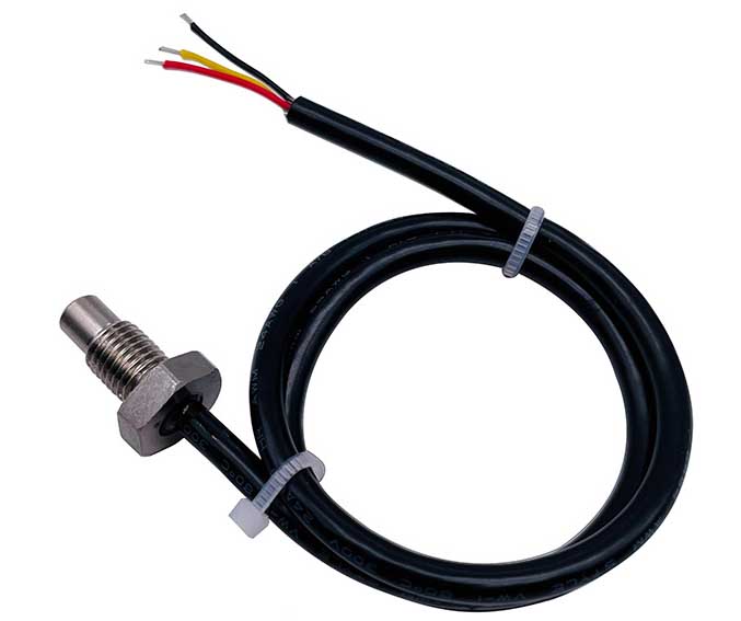 |
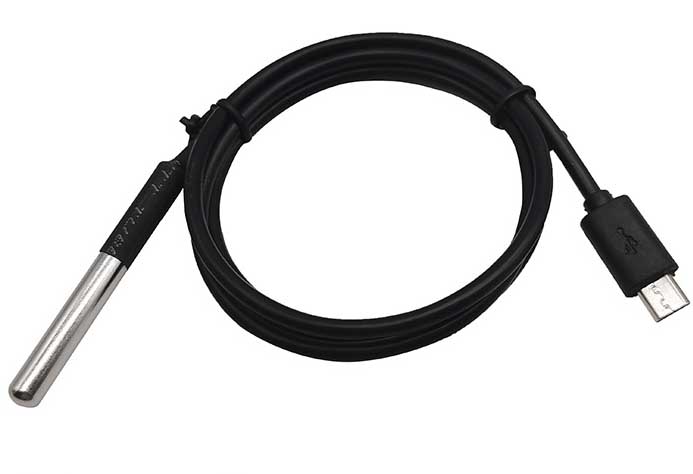 |
| M8 threaded head probe for DS18B20 digital temperature sensor | Digital temperature sensor with USB interface, cable length 1 meter |
3. Introduction to DS18B20 timing
1) Reset
enter
Time t0-t1: reset pulse 480-960us;
Time t1-t2: release the bus 15-60us;
Detection
Time t2-t3: The dotted line part is controlled by DS18B20. A low level of 60-240us indicates a successful reset, otherwise it fails;
Time t3-t4: Release the bus
2) Write operation
Write 0 timing
enter
t0-15us: Keep low level, input 0;
Detection
15-60us: Detect whether i/o is low level;
Input interval>1us
Write 1 timing
enter
t0-15us: Pull high level, input 1;
Detection
15-60us: Detect whether i/o is high level
Input interval>1us
3) Read operation
t0-t1: keep low level for 4us
t1-15us: DS18B20 or pull-up resistor works, low level or high level is read out
15us-60us: Release the bus
3. Temperature of DS18B20
1. Temperature format table of DS18B20
There are 16 bits in total. We use the first 5 bits to represent the sign bit and the last 11 bits to represent the value.
2. Temperature data table of DS18B20
125℃/2000 = 0.0625
When the sign bit is 0, it represents a positive number, and 0.0625*hex gets the temperature value;
When the sign bit is 1, it represents a negative number, and the obtained value (reverse value + 1) * 0.0625 is obtained to obtain the temperature value;
4. Procedure
1. Start temperature conversion
1) Reset DS18B20;
2) Issue the Skip Rom command (CCH) [only applicable to only one DS18B20];
3) Issue the convert command (44H)
2. Read the temperature
1) Reset DS18B20;
2) Issue the Skip Rom command (CCH);
3) Issue the convert command (BEH);
4) Read 2 bytes of temperature;
5) Temperature format conversion;
program
main.h
# ifndef _MAIN_H_
# define _MAIN_H_
#include
#include
sbit DQ = P3^2;
sbit RS = P1^0;
sbit RW = P1^1;
sbit EN = P1^5;
sbit BUSY = P0^7;
typedef unsigned char uint8;
typedef unsigned int uint16;
typedef int int16;
#define nops() {_nop_();_nop_();_nop_();_nop_();}
#endif
main.c
#include "main.h"
void delay(uint16 n)
{
while(n--);
}
void DB18B20_reset(void)
{
bit flag = 1; //The program has been changed
while(flag)
{
DQ = 1;
nops();
DQ = 0;
delay(50);
DQ = 1;
delay(5);
flag = DQ;
delay(20);
}
DQ = 1;
delay(20);
}
void write_byte(uint8 byte)
{
uint8 i ;
for(i=0; i<8; i++)
{
DQ = 1;
_nop_() ;
DQ = 0;
nops();
DQ = byte&0x01;
delay(6);
byte>>=1;
}
DQ = 1;
_nop_() ; //A short delay should be sufficient.
}
uint8 read_byte(void)
{
uint8 i, dat =0;
for(i=0; i<8; i++)
{
DQ = 1;
_nop_() ;
DQ = 0;
nops();
DQ = 1;
nops();
dat>>=1;
if(DQ)
dat |= 0x80 ;
delay(6);
}
DQ = 1;
_nop_() ;
return dat;
}
void start_temp_sensor(void)
{
DB18B20_reset();
write_byte(0xcc);
write_byte(0x44);
}
int16 read_temp(void)
{
uint8 tempdata[2];
int16 temp; //The sign bit of the data depends on whether the output requires a sign.
DB18B20_reset();
write_byte(0xcc);
write_byte(0xBE);
tempdata[0] = read_byte();
tempdata[1] = read_byte();
temp = tempdata[1];
temp<<=8;
temp |= tempdata[0]; //Convert to decimal code. I don’t understand. Please help me.
temp>>=4;
return temp;
}
void wait(void)
{
P0 = 0xFF;
do
{
RS = 0;
RW = 1;
EN = 0;
EN = 1;
}while (BUSY == 1);
EN = 0;
}
void w_dat(uint8 dat)
{
wait();
EN = 0;
P0 = dat;
RS = 1;
RW = 0;
EN = 1;
EN = 0;
}
void w_cmd(uint8 cmd)
{
wait();
EN = 0;
P0 = cmd;
RS = 0;
RW = 0;
EN = 1;
EN = 0;
}
void w_hexnum(uint16 dat)
{
w_dat(dat/10 + 0);
w_dat(dat + 0);
w_dat(0xDF);
w_dat(C);
}
void Init_LCD1602(void)
{
w_cmd(0x38); // 16*2 display, 5*7 dot matrix, 8-bit data interface
w_cmd(0x0C); //The display is on, the cursor is on, and the cursor is allowed to flash.
w_cmd(0x06); //The text does not move and the cursor automatically moves to the right
w_cmd(0x01); // Clear screen
}
void main(void)
{
int16 ans;
Init_LCD1602();
while(1)
{
start_temp_sensor(); //Why a delay is needed here;
ans = read_temp();
w_cmd(0x80);
w_hexnum(ans);
}
}


