Design Circuit Diagram of DS18B20 Temperature Sensor
Temperature is closely related to industrial and agricultural production. The measurement and control of temperature are the guarantee for improving production efficiency, ensuring product quality, ensuring production safety and saving energy. With the continuous development of industry, due to the universality of temperature measurement, the market share of temperature sensors has greatly increased, ranking first among sensors. The digital temperature sensor DS18B20 is the world's first temperature sensor to support the "one-cable bus" interface. Now, the new generation of DS18B20 temperature sensor is smaller, more economical and more flexible. The DS18B20 temperature sensor measures the temperature range from -55℃ to +125℃. In the range of -10℃~+85℃, the accuracy is ±0.5℃. The on-site temperature is directly transmitted digitally via the "one-line bus", which greatly improves the system's anti-interference capability. Based on the importance of the DS18B20 temperature sensor, the editor has compiled the working principle and application circuit diagram of the DS18B20 temperature sensor for your reference.
1. Working principle of DS18B20 temperature sensor (working principle of thermal resistance)
The working principle block diagram of DS18B20 temperature sensor is shown in the figure:
 DS18B20 temperature sensor working principle block diagram
The oscillation frequency of the low temperature coefficient crystal oscillator in the figure is very little affected by temperature, and is used to generate a fixed frequency pulse signal and send it to the counter 1. The oscillation frequency of the high temperature coefficient crystal oscillator changes significantly with temperature changes, and the generated signal is used as the pulse input of counter 2. Counter 1 and the temperature register are preset at a base value corresponding to -55°C. Counter 1 counts down the pulse signal generated by the low temperature coefficient crystal oscillator. When the preset value of counter 1 decreases to 0, the value of the temperature register will be increased by 1, the preset value of counter 1 will be reloaded, and counter 1 will restart counting the pulse signals generated by the low temperature coefficient crystal oscillator. This cycle continues until counter 2 counts to 0, then stops accumulating the temperature register value. At this time, the value in the temperature register is the measured temperature. The slope accumulator is used to compensate and correct the nonlinearity in the temperature measurement process, and its output is used to correct the preset value of counter 1.
2. Application circuit of DS18B20 temperature sensor
1.DS18B20 temperature sensor parasitic power supply circuit diagram
Characteristics of parasitic power supply:
(1) When performing remote temperature measurement, no local power supply is required.
(2) ROM can be read without conventional power supply.
(3) The circuit is simpler, using only one I/O port to measure temperature.
(4) It is only suitable for use when measuring temperature with a single temperature sensor, and is not suitable for use in battery-powered systems.
DS18B20 temperature sensor parasitic power supply mode
2. DS18B20 temperature sensor parasitic power supply strong pull-up power supply circuit diagram
The strong pull-up power supply mode can solve the problem of insufficient current supply, so it is also suitable for multi-point temperature measurement applications. The disadvantage is that it takes up one more I/O port line for strong pull-up switching.
DS18B20 temperature sensor parasitic power supply strong pull-up power supply mode
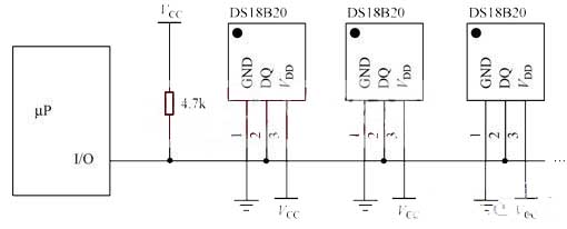
3. External power supply mode of DS18B20 temperature sensor
The external power supply method is the best working method for the DS18B20 temperature sensor. The work is stable and reliable, the anti-interference ability is strong, and the circuit is relatively simple, a stable and reliable multi-point temperature monitoring system can be developed, as shown in the figure.
Multi-point temperature measurement circuit diagram with external power supply
3. Precautions when using DS18B20 temperature sensor
(1) Small hardware overhead requires relatively complex software to compensate. Since serial data transmission is used between the DS18B20 temperature sensor and the microprocessor, the read and write timing must be strictly guaranteed when reading and writing the DS18B20. Otherwise, the temperature measurement results will not be read. When using high-level languages such as PL/M and C for system programming, it is best to use assembly language to implement the DS18B20 operation part.
(2) The relevant information on the DS18B20 temperature sensor does not mention the number of DS18B20s connected to a single bus, which may easily lead people to mistakenly believe that any number of DS18B20s can be connected. In practical applications this is not the case.
(3) The bus cable connected to the DS18B20 temperature sensor has a length limit. When designing a long-distance temperature measurement system using DS18B20, the bus distributed capacitance and impedance matching issues must be fully considered.
(4) In the temperature measurement program design of the DS18B20 temperature sensor, after issuing a temperature conversion command to the DS18B20, the program always waits for the return signal from the DS18B20. Once a certain DS18B20 has poor contact or disconnection, when the program reads the DS18B20, there will be no return signal and the program will enter an infinite loop.
(5) It is recommended to use shielded 4-core twisted pair for temperature measurement cable. One pair of wires is connected to the ground wire and signal wire, the other pair is connected to VCC and ground wire, and the shielding layer is grounded at a single point at the source end.
Conclusion
The DS18B20 temperature sensor (temperature sensor application example) has the characteristics of a wider voltage range, and DS18B20 supports multi-point networking functions. This article introduces the working principle of the DS18B20 temperature sensor and combines it with the application circuit diagram of the DS18B20 temperature sensor. I believe everyone has an understanding of the working principle of the DS18B20 temperature sensor and its application circuit diagram. Finally, the editor reminds everyone that the precautions when using the DS18B20 temperature sensor cannot be ignored to avoid unnecessary losses.
1. Working principle of DS18B20 temperature sensor (working principle of thermal resistance)
The working principle block diagram of DS18B20 temperature sensor is shown in the figure:
The oscillation frequency of the low temperature coefficient crystal oscillator in the figure is very little affected by temperature, and is used to generate a fixed frequency pulse signal and send it to the counter 1. The oscillation frequency of the high temperature coefficient crystal oscillator changes significantly with temperature changes, and the generated signal is used as the pulse input of counter 2. Counter 1 and the temperature register are preset at a base value corresponding to -55°C. Counter 1 counts down the pulse signal generated by the low temperature coefficient crystal oscillator. When the preset value of counter 1 decreases to 0, the value of the temperature register will be increased by 1, the preset value of counter 1 will be reloaded, and counter 1 will restart counting the pulse signals generated by the low temperature coefficient crystal oscillator. This cycle continues until counter 2 counts to 0, then stops accumulating the temperature register value. At this time, the value in the temperature register is the measured temperature. The slope accumulator is used to compensate and correct the nonlinearity in the temperature measurement process, and its output is used to correct the preset value of counter 1.
 |
 |
| Design digital temperature sensor circuit diagram | How the DS18B20 digital temperature sensor works |
2. Application circuit of DS18B20 temperature sensor
1.DS18B20 temperature sensor parasitic power supply circuit diagram
Characteristics of parasitic power supply:
(1) When performing remote temperature measurement, no local power supply is required.
(2) ROM can be read without conventional power supply.
(3) The circuit is simpler, using only one I/O port to measure temperature.
(4) It is only suitable for use when measuring temperature with a single temperature sensor, and is not suitable for use in battery-powered systems.
DS18B20 temperature sensor parasitic power supply mode
2. DS18B20 temperature sensor parasitic power supply strong pull-up power supply circuit diagram
The strong pull-up power supply mode can solve the problem of insufficient current supply, so it is also suitable for multi-point temperature measurement applications. The disadvantage is that it takes up one more I/O port line for strong pull-up switching.
DS18B20 temperature sensor parasitic power supply strong pull-up power supply mode
3. External power supply mode of DS18B20 temperature sensor
The external power supply method is the best working method for the DS18B20 temperature sensor. The work is stable and reliable, the anti-interference ability is strong, and the circuit is relatively simple, a stable and reliable multi-point temperature monitoring system can be developed, as shown in the figure.
Multi-point temperature measurement circuit diagram with external power supply
3. Precautions when using DS18B20 temperature sensor
(1) Small hardware overhead requires relatively complex software to compensate. Since serial data transmission is used between the DS18B20 temperature sensor and the microprocessor, the read and write timing must be strictly guaranteed when reading and writing the DS18B20. Otherwise, the temperature measurement results will not be read. When using high-level languages such as PL/M and C for system programming, it is best to use assembly language to implement the DS18B20 operation part.
(2) The relevant information on the DS18B20 temperature sensor does not mention the number of DS18B20s connected to a single bus, which may easily lead people to mistakenly believe that any number of DS18B20s can be connected. In practical applications this is not the case.
(3) The bus cable connected to the DS18B20 temperature sensor has a length limit. When designing a long-distance temperature measurement system using DS18B20, the bus distributed capacitance and impedance matching issues must be fully considered.
(4) In the temperature measurement program design of the DS18B20 temperature sensor, after issuing a temperature conversion command to the DS18B20, the program always waits for the return signal from the DS18B20. Once a certain DS18B20 has poor contact or disconnection, when the program reads the DS18B20, there will be no return signal and the program will enter an infinite loop.
(5) It is recommended to use shielded 4-core twisted pair for temperature measurement cable. One pair of wires is connected to the ground wire and signal wire, the other pair is connected to VCC and ground wire, and the shielding layer is grounded at a single point at the source end.
Conclusion
The DS18B20 temperature sensor (temperature sensor application example) has the characteristics of a wider voltage range, and DS18B20 supports multi-point networking functions. This article introduces the working principle of the DS18B20 temperature sensor and combines it with the application circuit diagram of the DS18B20 temperature sensor. I believe everyone has an understanding of the working principle of the DS18B20 temperature sensor and its application circuit diagram. Finally, the editor reminds everyone that the precautions when using the DS18B20 temperature sensor cannot be ignored to avoid unnecessary losses.


