Arduino Collects Multiple DS18B20 Temperature Values
DS18B20 is a digital single-bus intelligent temperature sensor from DALLAS Semiconductor Company in the United States. Compared with traditional thermistors, it can directly read the measured temperature, and can achieve 9 to 12-digit digital value reading through simple programming according to actual requirements. Reading or writing information from DS18B20 only requires one line (single bus) to read and write, and the bus itself can also provide power to the connected device without the need for an additional power supply.
This blog post will implement LabVIEW to control Arduino to collect multiple DS18B20 temperature values. Regarding LabVIEW controlling Arduino, we have already explained the collection methods of many types of temperature sensors in the basics. For details, please see the following link:
LabVIEW controls Arduino to collect the value of LM35 temperature sensor (Basics - 12)
LabVIEW controls Arduino to collect the thermistor temperature value (Basics - 13)
2. Project structure
This project will introduce the use of 2 DS18B20 sensors, Arduino Uno and LabVIEW to form a multi-channel temperature digital measurement system. The block diagram of the multi-channel temperature digital measurement system is shown below:
Among them, two DS18B20 temperature sensors are connected to a single bus in parallel, and Arduino Uno serves as the slave computer, responsible for the reading, writing and data transmission of DS18B20. The display software written in LabVIEW serves as the host computer, and the host and slave computers use the USB-TTL interface to achieve communication.
3. Hardware environment
Connect the Vcc and GND of the DS18B20 temperature sensor to the +5V and GND of the Arduino Uno controller respectively to provide power to the DS18B20. The DQ pin of DS18B20 is connected to the Arduino Uno controller digital pin D2, and a 4.7KΩ pull-up resistor is connected, because the DQ pin of DS18B20 needs to add a pull-up resistor for normal operation. The hardware connection diagram of the multi-channel temperature digital measurement system is shown below:
4. Arduino functional design
In the upper and lower computer temperature monitoring system based on Arduino and LabVIEW, the Arduino Uno control board needs to complete the following functions: receiving and judging commands and collecting and transmitting temperature data. The Arduino Uno control board receives commands from the host computer through the serial port, analyzes and obtains valid commands, reads and writes the DS18B20 sensor to obtain the temperature, and uploads the temperature data to the LabVIEW software.
The Arduino Uno controller is responsible for reading the temperature acquisition command sent by the LabVIEW host computer, and reading the corresponding DS18B20 sensor to obtain the temperature data, and sends it back to the host computer LabVIEW software through the serial port. The program code for the Arduino Uno controller is as follows:
#include <OneWire.h>#include <DallasTemperature.h>#define ONE_WIRE_BUS 2 //DS18B20 is connected to Arduino digital port 2
#define T1_COMMAND 0x80 //Collect command words #define T2_COMMAND 0x81 //Collect command words
OneWire oneWire(ONE_WIRE_BUS);DallasTemperature sensors(&oneWire);
byte comdata[3]={0};
//Define array data to store serial port command data void receive_data(void);
//Receive serial port data void test_do_data(void);
//Test whether the serial port data is correct and execute the command void setup(){ Serial.begin(9600); // Start up the library sensors.begin();} void loop(){ while (Serial.available() > 0)
//Continuously detect whether there is data on the serial port { receive_data();
//Accept serial port data test_do_data();
//Test whether the data is correct and execute the command }} void receive_data(void) { int i ; for(i=0;i<3;i++) { comdata[i] =Serial.read();
//Delay for a while to let the serial port cache prepare the next byte. Failure to delay may result in data loss delay(2); }} void test_do_data(void)
//Test and execute the command { if(comdata[0] == 0x55) /
/0x55 and 0xAA are both valid commands to determine whether { if(comdata[1] == 0xAA) { switch (comdata[2]) { case T1_COMMAND: sensors.requestTemperatures();
//ratures Serial.print(sensors.getTempCByIndex(0)); break; case T2_COMMAND: sensors.requestTemperatures(); /
/ Set temperatures Serial.print(sensors.getTempCByIndex(1)); break; } } }}
5. LabVIEW functional design
The LabVIEW host computer part needs to complete the following functions: send temperature acquisition commands to the Arduino controller of the host computer. The ino controller receives commands from the host computer through the serial port and transmits the data back after completing the collection of temperature data. The LabVIEW software displays the returned temperature data on the front panel.
5.1. Front panel design
The LabVIEW front panel is divided into temperature display and sensor selection terminals. The sensor selection terminal is used to determine the currently monitored sensor, and the waveform data is used to display the changing trend of the temperature data. The front panel of the LabVIEW host computer of the multi-channel temperature digital measurement system is shown in the figure below:
5.2. Program block diagram design
The structure of the main program of the LabVIEW host computer is a sequential structure + While loop. First, in the frame of the sequence structure, serial port communication is initialized through the set serial port number and the waveform chart is cleared. Then, the program enters the While loop and flat sequence structure, sends the command code for sensor 1 or sensor 2 temperature measurement to the Arduino Uno controller, waits for 100ms, and after receiving the returned temperature, displays it on the front panel and displays the temperature waveform. Finally close the serial communication.
Use the radio buttons on the front panel to select the sensor to be measured, and then send the corresponding temperature acquisition command code to the Arduino Uno controller. The command code for sensor 1 is 0x55AA80, and the command code for sensor 2 is 0x55AA81. And by delaying 800 milliseconds, the function of sampling once per second is achieved. The program block diagram corresponding to sensor 1 and sensor 2 is shown below:
This blog post will implement LabVIEW to control Arduino to collect multiple DS18B20 temperature values. Regarding LabVIEW controlling Arduino, we have already explained the collection methods of many types of temperature sensors in the basics. For details, please see the following link:
LabVIEW controls Arduino to collect the value of LM35 temperature sensor (Basics - 12)
LabVIEW controls Arduino to collect the thermistor temperature value (Basics - 13)
 |
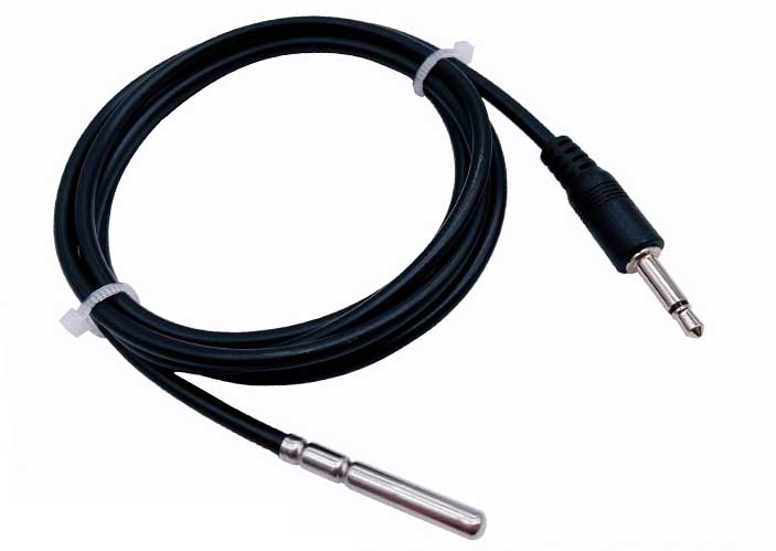 |
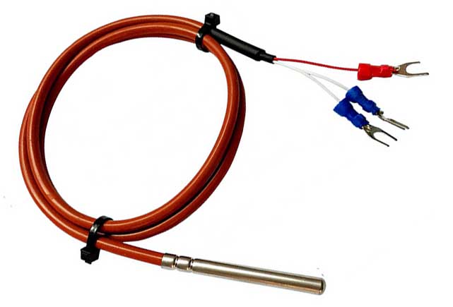
| DS18B20 digital sensor with 1M, 2M, 3M, 4M shielded wire | DS18b20 temperature sensor + 3.5mm headphone plug |
2. Project structure
This project will introduce the use of 2 DS18B20 sensors, Arduino Uno and LabVIEW to form a multi-channel temperature digital measurement system. The block diagram of the multi-channel temperature digital measurement system is shown below:
Among them, two DS18B20 temperature sensors are connected to a single bus in parallel, and Arduino Uno serves as the slave computer, responsible for the reading, writing and data transmission of DS18B20. The display software written in LabVIEW serves as the host computer, and the host and slave computers use the USB-TTL interface to achieve communication.
3. Hardware environment
Connect the Vcc and GND of the DS18B20 temperature sensor to the +5V and GND of the Arduino Uno controller respectively to provide power to the DS18B20. The DQ pin of DS18B20 is connected to the Arduino Uno controller digital pin D2, and a 4.7KΩ pull-up resistor is connected, because the DQ pin of DS18B20 needs to add a pull-up resistor for normal operation. The hardware connection diagram of the multi-channel temperature digital measurement system is shown below:
4. Arduino functional design
In the upper and lower computer temperature monitoring system based on Arduino and LabVIEW, the Arduino Uno control board needs to complete the following functions: receiving and judging commands and collecting and transmitting temperature data. The Arduino Uno control board receives commands from the host computer through the serial port, analyzes and obtains valid commands, reads and writes the DS18B20 sensor to obtain the temperature, and uploads the temperature data to the LabVIEW software.
The Arduino Uno controller is responsible for reading the temperature acquisition command sent by the LabVIEW host computer, and reading the corresponding DS18B20 sensor to obtain the temperature data, and sends it back to the host computer LabVIEW software through the serial port. The program code for the Arduino Uno controller is as follows:
#include <OneWire.h>#include <DallasTemperature.h>#define ONE_WIRE_BUS 2 //DS18B20 is connected to Arduino digital port 2
#define T1_COMMAND 0x80 //Collect command words #define T2_COMMAND 0x81 //Collect command words
OneWire oneWire(ONE_WIRE_BUS);DallasTemperature sensors(&oneWire);
byte comdata[3]={0};
//Define array data to store serial port command data void receive_data(void);
//Receive serial port data void test_do_data(void);
//Test whether the serial port data is correct and execute the command void setup(){ Serial.begin(9600); // Start up the library sensors.begin();} void loop(){ while (Serial.available() > 0)
//Continuously detect whether there is data on the serial port { receive_data();
//Accept serial port data test_do_data();
//Test whether the data is correct and execute the command }} void receive_data(void) { int i ; for(i=0;i<3;i++) { comdata[i] =Serial.read();
//Delay for a while to let the serial port cache prepare the next byte. Failure to delay may result in data loss delay(2); }} void test_do_data(void)
//Test and execute the command { if(comdata[0] == 0x55) /
/0x55 and 0xAA are both valid commands to determine whether { if(comdata[1] == 0xAA) { switch (comdata[2]) { case T1_COMMAND: sensors.requestTemperatures();
//ratures Serial.print(sensors.getTempCByIndex(0)); break; case T2_COMMAND: sensors.requestTemperatures(); /
/ Set temperatures Serial.print(sensors.getTempCByIndex(1)); break; } } }}
5. LabVIEW functional design
The LabVIEW host computer part needs to complete the following functions: send temperature acquisition commands to the Arduino controller of the host computer. The ino controller receives commands from the host computer through the serial port and transmits the data back after completing the collection of temperature data. The LabVIEW software displays the returned temperature data on the front panel.
5.1. Front panel design
The LabVIEW front panel is divided into temperature display and sensor selection terminals. The sensor selection terminal is used to determine the currently monitored sensor, and the waveform data is used to display the changing trend of the temperature data. The front panel of the LabVIEW host computer of the multi-channel temperature digital measurement system is shown in the figure below:
5.2. Program block diagram design
The structure of the main program of the LabVIEW host computer is a sequential structure + While loop. First, in the frame of the sequence structure, serial port communication is initialized through the set serial port number and the waveform chart is cleared. Then, the program enters the While loop and flat sequence structure, sends the command code for sensor 1 or sensor 2 temperature measurement to the Arduino Uno controller, waits for 100ms, and after receiving the returned temperature, displays it on the front panel and displays the temperature waveform. Finally close the serial communication.
Use the radio buttons on the front panel to select the sensor to be measured, and then send the corresponding temperature acquisition command code to the Arduino Uno controller. The command code for sensor 1 is 0x55AA80, and the command code for sensor 2 is 0x55AA81. And by delaying 800 milliseconds, the function of sampling once per second is achieved. The program block diagram corresponding to sensor 1 and sensor 2 is shown below:


