Application of DS18B20 temperature sensor
1-Wire bus technology has the characteristics of saving I/O resources, simple structure, low cost, easy bus expansion and convenient maintenance. Therefore, it is widely used in distributed temperature measurement systems. The single-bus intelligent temperature sensor DS18B20 produced by the American DALLAS company is a typical product using 1-Wire bus technology. DS18B20 transmits specific command sequences and communicates data through a single wire according to the 1-Wire protocol. A very important feature of this series of products is that each device is written with a unique 64-bit ROM code or serial number before leaving the factory, and the least significant byte is the family code. Represents the type of device. For example, the family code of DS1990A is 01H, and the family code of DS18B20 is 28H. Because multiple 1-Wire devices of the same series or different series can be connected to the same 1-Wire bus at the same time, the host must be able to determine how to correctly access each device on the 1-Wire bus. The family code in the 64-bit ROM code provides the type of device, and the following 6 bytes are the unique serial number of the device to distinguish different devices of the same series. This serial number serves as the address of the device on the 1-Wire bus. In this way, all the devices on the 1-Wire bus together with the host form a micro LAN. They communicate through a common line.
 2. Digital temperature sensor characteristics and function block diagram.
The core function of DS18B20 is that it can be directly converted into digital quantities. Since each smart temperature sensor DS18B20 has a unique 64-bit serial number. Allows multiple DS18B20 to work on the same bus. Therefore, one single-chip microcomputer can be used to control multiple digital temperature sensors DS18B20 in a large range, which is often used in ambient temperature control, temperature monitoring systems, and process monitoring and control systems. The most significant byte of the 1-Wire device's 64-bit serial number is the cyclic redundancy check CRC code. The value is based on the previous 56 bits of data. When the system host starts communicating with a device, it can read 8 ROM bytes starting from the low-order bit, which is the 64-bit serial number.
The temperature measurement range of the 1-Wire bus technology temperature sensor DS18B20 is - 55℃ ~ + 125℃. The scratch pad memory contains a two-byte temperature register used to store the digital output of the temperature sensor. In addition, a byte alarm upper limit TH and a byte alarm lower limit TL register are provided. There is also a byte configuration register. The configuration register allows the user to set the resolution to 9 to 12 bits. Corresponding to the temperature values 0.5℃, 0.25℃, 0.125℃ and 0.0625℃ respectively. TH, TL and configuration registers can be stored in EEPROM, so when the system is powered off, the data in TH, TL and configuration registers will still be saved. The temperature sensor DS18B20 functional block of 1-Wire bus technology is shown in Figure 1.
Figure 1 1-Wire technology temperature sensor DS18B20 functional block diagram
3. Digital temperature sensor ROM commands and function commands.
In order to make the temperature sensor DS18B20 of 1-Wire bus technology work normally, relevant commands need to be executed in a certain order. First perform initialization, secondly execute ROM commands, and finally execute DS18B20 function commands. There are 5 commonly used ROM commands. Each command is one byte. Before sending the DS18B20 function command, the main CPU must issue the appropriate ROM command. The five operating commands for ROM include ROM search command (code: F0H), ROM command (code: 33H), match ROM command (code: 55H), skip ROM command (code: CCH) and search alarm command (code: ECH).
After the main CPU uses the ROM command, if it accesses the slave device DS18B20 that it wants to communicate with, the main CPU can issue a DS18B20 function command. There are mainly 5 functional commands for the temperature sensor DS18B20 using 1-Wire bus technology. These commands allow the main CPU to read or write the DS18B20's scratch memory, initiate temperature conversions, and determine the mode of the power supply. The DS18B20 function commands are described below.
1. The temperature conversion command (code 44H) causes the DS18B20 to start conversion. The converted temperature data is stored in the two-byte temperature register.
2. The write note memory command (code 4EH) allows the main CPU to write 3 bytes of data to the note memory. The first data byte is written to the TH register, the second data byte is written to the TL register, and the third data byte is written to the configuration register. Data is written starting from the least significant bit. Three bytes must be written before the main CPU issues a reset pulse.
3. The read note memory command (code BEH) allows the main CPU to read the contents of the note memory. Data transfer starts from the least significant bit of byte 0 to byte 8. The 9-byte contents of the memo memory are read out. Byte 8 is the CRC check code. If only part of the bytes in the scratch pad memory need to be read out, the main CPU can send a reset pulse at any time to terminate the read operation.
4. The copy note memory command (code 48H) will copy the note memory bytes 2, 3, and 4, that is, the contents of TH, TL and configuration registers, to EEPROM.
5. The recall command from EEPROM (code B8H) will recall the contents of TH, TL and configuration registers from EEPROM and place the data into bytes 2, 3 and 4 of the scratch pad memory. Recalling the command from EEPROM (code B8H) will be automatically executed when powering on.
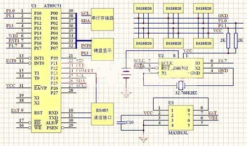
4. Fire alarm system hardware components
The fire alarm system consists of AT89C51, real-time clock circuit DS1302, keyboard and display circuit, RS485 communication circuit, watchdog circuit composed of MAX813L, serial E2PROM memory circuit, etc. Using multiple sensors to measure the temperature in different rooms, you can set the upper alarm limits for different rooms, and realize the display and alarm of the corresponding temperatures in multiple rooms.
The hardware composition of the fire alarm system is shown in Figure 2.
Figure 2, Fire alarm system hardware composition diagram
5. 1-Wire bus technology digital temperature sensor power supply method
There are two types of power supplies for DS18B20. External power supply mode and parasitic power supply mode. The external power supply method is shown in Figure 3. The pin VDD in Figure 3 is connected to the external power supply. The parasitic power supply method does not require an external power supply as shown in Figure 4. When working in parasitic power supply mode, both VDD and GND are connected to ground. Very useful when remote temperature detection is required and space is limited. In Figure 3, when the 1-Wire bus is high, DS18B20 "steals" power from the 1-Wire bus through pin DQ, and the stolen charge supplies power to the bus. When the bus is low, the charge stored on the parasitic supply capacitance powers the sensor. When DS18B20 is used in parasitic power supply mode, VDD must be connected to ground. However, in the parasitic power supply mode, when the DS18B20 performs temperature conversion and copies the contents of the scratch pad memory to the EEPROM, the operating current can reach 1.5mA. This current can cause the voltage to drop significantly and prevent the sensor from functioning properly. In order to ensure that the DS18B20 has sufficient supply current, a strong enough pull-up must be provided on the bus when performing temperature conversion and copying the contents of the scratch pad memory to EEPROM. A MOSFET tube can be used to pull up the bus, as shown in Figure 4. Generally, when the detected temperature exceeds 100°C, it is recommended not to use parasitic power supply but to use external power supply. Because at such high temperatures, it is impossible for the DS18B20 to maintain data communication due to the high leakage current. Therefore, when conditions permit, try to use external power supply.
Figure 3, external power supply method of DS18B20
Figure 4, Parasitic power supply mode of DS18B20
6. Temperature collection and processing flow chart
The fire alarm system designed based on AT89C51 microcontroller uses intelligent temperature sensor DS18B20. After correctly reading the 64-bit serial number, a temperature reading program needs to be written according to strict timing requirements. The microcontroller must follow the command flow of DS18B20 to control the temperature conversion of DS18B20. First, the initialization sequence is executed, and then the microcontroller issues a skip ROM command (code is CCH). This command is for all online DS18B20. The microcontroller then issues a start conversion command (code 44H) to start DS18B20 to complete the temperature conversion. For 12-bit resolution, a delay of 750ms is required. Then the initialization sequence is executed, and then the microcontroller issues a match ROM command (code 55H) and a 64-bit serial number on the data line, and then issues a read 9-byte command (code BEH). You can read the corresponding correct temperature after completing the temperature conversion of the corresponding serial number of the intelligent temperature sensor DS18B20. The temperature acquisition and processing flow chart based on DS18B20 is shown in Figure 5.
Figure 5 DS18B20 temperature acquisition and processing program flow chart based on 1-Wire technology
7. Conclusion
The traditional temperature measurement method is to transmit the analog signal to the sampling circuit for A/D conversion. In order to obtain higher accuracy, it is necessary to solve the problem of multi-point measurement switching and zero-point drift of the amplification circuit. The emergence of 1-Wire bus technology digital temperature sensors can better solve the above problems. The author's innovation in this article is to apply 1-Wire bus technology, use multiple digital temperature sensors to design a fire alarm system, analyze the sensor power supply mode and characteristics, and elaborate on the digital temperature sensor ROM commands and function commands. Based on AT89C51, the real-time clock display circuit, keyboard display circuit, serial memory circuit, RS485 communication circuit, watchdog circuit, etc. are designed, and the hardware composition diagram of the fire alarm system is explained. Designed a flow chart for temperature acquisition, and written a program to complete the correct display of temperature. The 1-Wire Technology temperature sensor DS18B20 converts the temperature signal directly into a serial digital signal for microcontroller processing. Multiple sensors are connected to a single bus interface, and the on-site temperature is directly transmitted in a digital bus format to easily form a distributed multi-point temperature measurement system. The use of 1-Wire bus technology digital temperature sensors effectively reduces costs, making application systems highly reliable and with long transmission distances. It has been well used in distributed temperature measurement fire alarm systems.
The core function of DS18B20 is that it can be directly converted into digital quantities. Since each smart temperature sensor DS18B20 has a unique 64-bit serial number. Allows multiple DS18B20 to work on the same bus. Therefore, one single-chip microcomputer can be used to control multiple digital temperature sensors DS18B20 in a large range, which is often used in ambient temperature control, temperature monitoring systems, and process monitoring and control systems. The most significant byte of the 1-Wire device's 64-bit serial number is the cyclic redundancy check CRC code. The value is based on the previous 56 bits of data. When the system host starts communicating with a device, it can read 8 ROM bytes starting from the low-order bit, which is the 64-bit serial number.
The temperature measurement range of the 1-Wire bus technology temperature sensor DS18B20 is - 55℃ ~ + 125℃. The scratch pad memory contains a two-byte temperature register used to store the digital output of the temperature sensor. In addition, a byte alarm upper limit TH and a byte alarm lower limit TL register are provided. There is also a byte configuration register. The configuration register allows the user to set the resolution to 9 to 12 bits. Corresponding to the temperature values 0.5℃, 0.25℃, 0.125℃ and 0.0625℃ respectively. TH, TL and configuration registers can be stored in EEPROM, so when the system is powered off, the data in TH, TL and configuration registers will still be saved. The temperature sensor DS18B20 functional block of 1-Wire bus technology is shown in Figure 1.
Figure 1 1-Wire technology temperature sensor DS18B20 functional block diagram
3. Digital temperature sensor ROM commands and function commands.
In order to make the temperature sensor DS18B20 of 1-Wire bus technology work normally, relevant commands need to be executed in a certain order. First perform initialization, secondly execute ROM commands, and finally execute DS18B20 function commands. There are 5 commonly used ROM commands. Each command is one byte. Before sending the DS18B20 function command, the main CPU must issue the appropriate ROM command. The five operating commands for ROM include ROM search command (code: F0H), ROM command (code: 33H), match ROM command (code: 55H), skip ROM command (code: CCH) and search alarm command (code: ECH).
After the main CPU uses the ROM command, if it accesses the slave device DS18B20 that it wants to communicate with, the main CPU can issue a DS18B20 function command. There are mainly 5 functional commands for the temperature sensor DS18B20 using 1-Wire bus technology. These commands allow the main CPU to read or write the DS18B20's scratch memory, initiate temperature conversions, and determine the mode of the power supply. The DS18B20 function commands are described below.
1. The temperature conversion command (code 44H) causes the DS18B20 to start conversion. The converted temperature data is stored in the two-byte temperature register.
2. The write note memory command (code 4EH) allows the main CPU to write 3 bytes of data to the note memory. The first data byte is written to the TH register, the second data byte is written to the TL register, and the third data byte is written to the configuration register. Data is written starting from the least significant bit. Three bytes must be written before the main CPU issues a reset pulse.
3. The read note memory command (code BEH) allows the main CPU to read the contents of the note memory. Data transfer starts from the least significant bit of byte 0 to byte 8. The 9-byte contents of the memo memory are read out. Byte 8 is the CRC check code. If only part of the bytes in the scratch pad memory need to be read out, the main CPU can send a reset pulse at any time to terminate the read operation.
4. The copy note memory command (code 48H) will copy the note memory bytes 2, 3, and 4, that is, the contents of TH, TL and configuration registers, to EEPROM.
5. The recall command from EEPROM (code B8H) will recall the contents of TH, TL and configuration registers from EEPROM and place the data into bytes 2, 3 and 4 of the scratch pad memory. Recalling the command from EEPROM (code B8H) will be automatically executed when powering on.
 |
 |
| Custom DS18B20 temperature sensor | IP68 waterproof DS18B20 temperature probe + 3.5mm audio plug |
4. Fire alarm system hardware components
The fire alarm system consists of AT89C51, real-time clock circuit DS1302, keyboard and display circuit, RS485 communication circuit, watchdog circuit composed of MAX813L, serial E2PROM memory circuit, etc. Using multiple sensors to measure the temperature in different rooms, you can set the upper alarm limits for different rooms, and realize the display and alarm of the corresponding temperatures in multiple rooms.
The hardware composition of the fire alarm system is shown in Figure 2.
Figure 2, Fire alarm system hardware composition diagram
5. 1-Wire bus technology digital temperature sensor power supply method
There are two types of power supplies for DS18B20. External power supply mode and parasitic power supply mode. The external power supply method is shown in Figure 3. The pin VDD in Figure 3 is connected to the external power supply. The parasitic power supply method does not require an external power supply as shown in Figure 4. When working in parasitic power supply mode, both VDD and GND are connected to ground. Very useful when remote temperature detection is required and space is limited. In Figure 3, when the 1-Wire bus is high, DS18B20 "steals" power from the 1-Wire bus through pin DQ, and the stolen charge supplies power to the bus. When the bus is low, the charge stored on the parasitic supply capacitance powers the sensor. When DS18B20 is used in parasitic power supply mode, VDD must be connected to ground. However, in the parasitic power supply mode, when the DS18B20 performs temperature conversion and copies the contents of the scratch pad memory to the EEPROM, the operating current can reach 1.5mA. This current can cause the voltage to drop significantly and prevent the sensor from functioning properly. In order to ensure that the DS18B20 has sufficient supply current, a strong enough pull-up must be provided on the bus when performing temperature conversion and copying the contents of the scratch pad memory to EEPROM. A MOSFET tube can be used to pull up the bus, as shown in Figure 4. Generally, when the detected temperature exceeds 100°C, it is recommended not to use parasitic power supply but to use external power supply. Because at such high temperatures, it is impossible for the DS18B20 to maintain data communication due to the high leakage current. Therefore, when conditions permit, try to use external power supply.
Figure 3, external power supply method of DS18B20
Figure 4, Parasitic power supply mode of DS18B20
6. Temperature collection and processing flow chart
The fire alarm system designed based on AT89C51 microcontroller uses intelligent temperature sensor DS18B20. After correctly reading the 64-bit serial number, a temperature reading program needs to be written according to strict timing requirements. The microcontroller must follow the command flow of DS18B20 to control the temperature conversion of DS18B20. First, the initialization sequence is executed, and then the microcontroller issues a skip ROM command (code is CCH). This command is for all online DS18B20. The microcontroller then issues a start conversion command (code 44H) to start DS18B20 to complete the temperature conversion. For 12-bit resolution, a delay of 750ms is required. Then the initialization sequence is executed, and then the microcontroller issues a match ROM command (code 55H) and a 64-bit serial number on the data line, and then issues a read 9-byte command (code BEH). You can read the corresponding correct temperature after completing the temperature conversion of the corresponding serial number of the intelligent temperature sensor DS18B20. The temperature acquisition and processing flow chart based on DS18B20 is shown in Figure 5.
Figure 5 DS18B20 temperature acquisition and processing program flow chart based on 1-Wire technology
7. Conclusion
The traditional temperature measurement method is to transmit the analog signal to the sampling circuit for A/D conversion. In order to obtain higher accuracy, it is necessary to solve the problem of multi-point measurement switching and zero-point drift of the amplification circuit. The emergence of 1-Wire bus technology digital temperature sensors can better solve the above problems. The author's innovation in this article is to apply 1-Wire bus technology, use multiple digital temperature sensors to design a fire alarm system, analyze the sensor power supply mode and characteristics, and elaborate on the digital temperature sensor ROM commands and function commands. Based on AT89C51, the real-time clock display circuit, keyboard display circuit, serial memory circuit, RS485 communication circuit, watchdog circuit, etc. are designed, and the hardware composition diagram of the fire alarm system is explained. Designed a flow chart for temperature acquisition, and written a program to complete the correct display of temperature. The 1-Wire Technology temperature sensor DS18B20 converts the temperature signal directly into a serial digital signal for microcontroller processing. Multiple sensors are connected to a single bus interface, and the on-site temperature is directly transmitted in a digital bus format to easily form a distributed multi-point temperature measurement system. The use of 1-Wire bus technology digital temperature sensors effectively reduces costs, making application systems highly reliable and with long transmission distances. It has been well used in distributed temperature measurement fire alarm systems.


