Microcontroller and DS18B20 Digital Thermometer
Temperature measurement starts from the thermal expansion and contraction of metal (substance). Commonly used detection methods include resistance type, thermocouple type, PN junction type, radiation type, fiber optic type and quartz resonance type. These detection methods are based on the principle that temperature changes cause changes in physical parameters (such as resistance value, thermoelectric potential, etc.). With the improvement of large-scale integrated circuit technology, a variety of integrated digital temperature sensors have emerged.
A design scheme for a small temperature measurement system based on MSP430 microcontroller is proposed here. The main controller uses MSP430 microcontroller, and the digital temperature sensor DS18B20 is connected to the microcontroller through a single bus (1-wire). The system has a simple structure and strong anti-interference ability. It is suitable for measuring on-site temperature in harsh environments and can be used in warehouse temperature measurement, building air conditioning control and production process monitoring.
1. Overall design of digital thermometer
The system uses a single-chip microcomputer as the main controller of the digital thermometer, an integrated digital temperature sensor as the temperature information collection unit, and an LCD and its driving components as the display unit. The basic block diagram of the system is shown in Figure 1.
Digital thermometer based on microcontroller and DS18B20
2. Hardware composition
The system's main controller uses TI's MSP430F1121A microcontroller, and the temperature sensor uses DALLAS's digital integrated temperature sensor DS18B20. Use 2 common cathode LED digital tubes and 2 CD4511 decoders to realize temperature display. The overall design circuit of the system is shown in Figure 2.
Digital thermometer based on microcontroller and DS18B20
2.1 Main controller
MSP430F1121A has a unique ultra-low power design with 5 low-power modes, which brings great convenience to the design of low-power instruments. The MSP430F1121A microcontroller is a Flash type, can be programmed repeatedly, and has an integrated A/D converter. Especially designed for smart meters and battery-powered portable devices. MSP430F1121A features are as follows:
1) High-efficiency 16-bit RISC core, 16-bit streamlined instruction structure, 27 instructions, 125 ns instruction cycle time, most instructions can be completed within 1 clock cycle;
2) 1.8~3.6 V low-voltage power supply, with multiple power-saving modes, extremely low power consumption, and one battery can work for 10 years;
3) Compared with other microcontrollers, microcontrollers with Flash can reduce power consumption by 5 times, which not only reduces the circuit board space but also reduces the system cost;
4) The fast startup time of 6 μs can extend the standby time and make startup faster, reducing battery power consumption;
5) Contains 12-bit fast ADC/Slope ADC, which can achieve high-precision slope A/D conversion with only one external resistor and one capacitor;
6) The chip is rich in resources, including ADC, PWM, several TIMEs, serial ports, watchdogs, comparators, analog signals, and powerful interrupt functions;
7) The SP430 series products can provide a variety of memory options, from 14-bit ADCs to mixed-signal peripherals for LCD driver circuits, simplifying the design of MSP430 in various applications;
8) ESD protection, strong anti-interference ability.
2.2 Decoding driver and display unit circuit
In order to visually display the operating status and working data of the digital system, the system's display module uses LG5011AH common cathode LED digital tube and CD4511 as the display decoding circuit. The input binary signal is translated into decimal numbers by CD4511, and then displayed by the digital tube, as shown in Figure 3.
Digital thermometer based on microcontroller and DS18B20
D, C, B, and A in Figure 3 are BCD code input terminals, which are respectively connected to the corresponding I/O ports of the main controller MSP430F1121A, a digital thermometer based on the microcontroller and DS18B20. BI is the blanking function terminal, LT is the lamp test terminal, and LE is the latch terminal.
The single-chip computer MSP430F1121A controls and processes the data measured by DS18B20 and transmits it to CD4511 in the form of 8421BCD code. CD4511 converts the BCD code into decimal digits and sends them to the digital tube for display.
4. Hardware components of temperature sensing of fire alarm system
The fire alarm system consists of AT89C51, real-time clock circuit DS1302, keyboard and display circuit, RS485 communication circuit, watchdog circuit composed of MAX813L, serial E2PROM memory circuit, etc. Using multiple sensors to measure the temperature in different rooms, you can set the upper alarm limits for different rooms, and realize the display and alarm of the corresponding temperatures in multiple rooms.
The hardware composition of the fire alarm system is shown in Figure 2.
Figure 2, Fire alarm system hardware composition diagram
5. 1-Wire bus technology digital temperature sensor power supply method
There are two types of power supplies for DS18B20. External power supply mode and parasitic power supply mode. The external power supply method is shown in Figure 3. The pin VDD in Figure 3 is connected to the external power supply. The parasitic power supply method does not require an external power supply as shown in Figure 4. When working in parasitic power supply mode, both VDD and GND are connected to ground. Very useful when remote temperature detection is required and space is limited. In Figure 3, when the 1-Wire bus is high, DS18B20 "steals" power from the 1-Wire bus through pin DQ, and the stolen charge supplies power to the bus. When the bus is low, the charge stored on the parasitic supply capacitance powers the sensor. When DS18B20 is used in parasitic power supply mode, VDD must be connected to ground. However, in the parasitic power supply mode, when the DS18B20 performs temperature conversion and copies the contents of the scratch pad memory to the EEPROM, the operating current can reach 1.5mA. This current can cause the voltage to drop significantly and prevent the sensor from functioning properly. In order to ensure that the DS18B20 has sufficient supply current, a strong enough pull-up must be provided on the bus when performing temperature conversion and copying the contents of the scratch pad memory to EEPROM. A MOSFET tube can be used to pull up the bus, as shown in Figure 4. Generally, when the detected temperature exceeds 100°C, it is recommended not to use parasitic power supply but to use external power supply. Because at such high temperatures, it is impossible for the DS18B20 to maintain data communication due to the high leakage current. Therefore, when conditions permit, try to use external power supply.
Figure 3 External power supply method of DS18B20
Figure 4 Parasitic power supply mode of DS18B20
6. Temperature collection and processing flow chart
The fire alarm system designed based on AT89C51 microcontroller uses intelligent temperature sensor DS18B20. After correctly reading the 64-bit serial number, a temperature reading program needs to be written according to strict timing requirements. The microcontroller must follow the command flow of DS18B20 to control the temperature conversion of DS18B20. First, the initialization sequence is executed, and then the microcontroller issues a skip ROM command (code is CCH). This command targets all online DS18B20s. The microcontroller then issues a start conversion command (code 44H) to start DS18B20 to complete the temperature conversion. For 12-bit resolution, a delay of 750ms is required. Then the initialization sequence is executed, and then the microcontroller issues a match ROM command (code 55H) and a 64-bit serial number on the data line, and then issues a read 9-byte command (code BEH). You can read the corresponding correct temperature after completing the temperature conversion of the corresponding serial number of the intelligent temperature sensor DS18B20. The temperature acquisition and processing flow chart based on DS18B20 is shown in Figure 5.
Figure 5 DS18B20 temperature acquisition and processing program flow chart based on 1-Wire technology
7. Conclusion
The traditional temperature measurement method is to transmit the analog signal to the sampling circuit for A/D conversion. In order to obtain higher accuracy, it is necessary to solve the problem of multi-point measurement switching and zero-point drift of the amplification circuit. The emergence of 1-Wire bus technology digital temperature sensors can better solve the above problems. The author's innovation in this article is to apply 1-Wire bus technology and design a fire alarm system using multiple digital temperature sensors. The sensor power supply mode and characteristics are analyzed, and the digital temperature sensor ROM commands and function commands are explained. Based on AT89C51, the real-time clock display circuit, keyboard display circuit, serial memory circuit, RS485 communication circuit, watchdog circuit, etc. are designed, and the hardware composition diagram of the fire alarm system is explained. Designed a flow chart for temperature acquisition, and written a program to complete the correct display of temperature. The 1-Wire Technology temperature sensor DS18B20 converts the temperature signal directly into a serial digital signal for microcontroller processing. Multiple sensors are connected to a single bus interface, and the on-site temperature is directly transmitted in a digital bus format to easily form a distributed multi-point temperature measurement system. The use of 1-Wire bus technology digital temperature sensors effectively reduces costs, making application systems highly reliable and with long transmission distances. It has been well used in distributed temperature measurement fire alarm systems.
A design scheme for a small temperature measurement system based on MSP430 microcontroller is proposed here. The main controller uses MSP430 microcontroller, and the digital temperature sensor DS18B20 is connected to the microcontroller through a single bus (1-wire). The system has a simple structure and strong anti-interference ability. It is suitable for measuring on-site temperature in harsh environments and can be used in warehouse temperature measurement, building air conditioning control and production process monitoring.
1. Overall design of digital thermometer
The system uses a single-chip microcomputer as the main controller of the digital thermometer, an integrated digital temperature sensor as the temperature information collection unit, and an LCD and its driving components as the display unit. The basic block diagram of the system is shown in Figure 1.
Digital thermometer based on microcontroller and DS18B20
2. Hardware composition
The system's main controller uses TI's MSP430F1121A microcontroller, and the temperature sensor uses DALLAS's digital integrated temperature sensor DS18B20. Use 2 common cathode LED digital tubes and 2 CD4511 decoders to realize temperature display. The overall design circuit of the system is shown in Figure 2.
Digital thermometer based on microcontroller and DS18B20
2.1 Main controller
MSP430F1121A has a unique ultra-low power design with 5 low-power modes, which brings great convenience to the design of low-power instruments. The MSP430F1121A microcontroller is a Flash type, can be programmed repeatedly, and has an integrated A/D converter. Especially designed for smart meters and battery-powered portable devices. MSP430F1121A features are as follows:
1) High-efficiency 16-bit RISC core, 16-bit streamlined instruction structure, 27 instructions, 125 ns instruction cycle time, most instructions can be completed within 1 clock cycle;
2) 1.8~3.6 V low-voltage power supply, with multiple power-saving modes, extremely low power consumption, and one battery can work for 10 years;
3) Compared with other microcontrollers, microcontrollers with Flash can reduce power consumption by 5 times, which not only reduces the circuit board space but also reduces the system cost;
4) The fast startup time of 6 μs can extend the standby time and make startup faster, reducing battery power consumption;
5) Contains 12-bit fast ADC/Slope ADC, which can achieve high-precision slope A/D conversion with only one external resistor and one capacitor;
6) The chip is rich in resources, including ADC, PWM, several TIMEs, serial ports, watchdogs, comparators, analog signals, and powerful interrupt functions;
7) The SP430 series products can provide a variety of memory options, from 14-bit ADCs to mixed-signal peripherals for LCD driver circuits, simplifying the design of MSP430 in various applications;
8) ESD protection, strong anti-interference ability.
2.2 Decoding driver and display unit circuit
In order to visually display the operating status and working data of the digital system, the system's display module uses LG5011AH common cathode LED digital tube and CD4511 as the display decoding circuit. The input binary signal is translated into decimal numbers by CD4511, and then displayed by the digital tube, as shown in Figure 3.
Digital thermometer based on microcontroller and DS18B20
 |
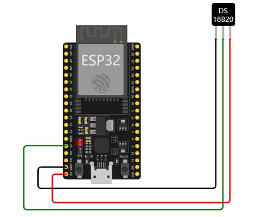 |
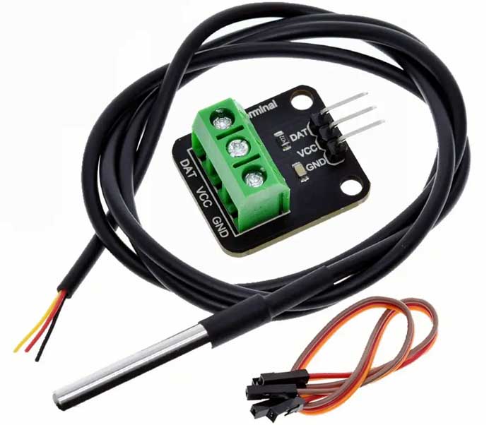
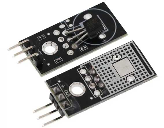
| DS18B20 temperature sensing module | ds18b20 temperature sensor driven on esp32 |
D, C, B, and A in Figure 3 are BCD code input terminals, which are respectively connected to the corresponding I/O ports of the main controller MSP430F1121A, a digital thermometer based on the microcontroller and DS18B20. BI is the blanking function terminal, LT is the lamp test terminal, and LE is the latch terminal.
The single-chip computer MSP430F1121A controls and processes the data measured by DS18B20 and transmits it to CD4511 in the form of 8421BCD code. CD4511 converts the BCD code into decimal digits and sends them to the digital tube for display.
4. Hardware components of temperature sensing of fire alarm system
The fire alarm system consists of AT89C51, real-time clock circuit DS1302, keyboard and display circuit, RS485 communication circuit, watchdog circuit composed of MAX813L, serial E2PROM memory circuit, etc. Using multiple sensors to measure the temperature in different rooms, you can set the upper alarm limits for different rooms, and realize the display and alarm of the corresponding temperatures in multiple rooms.
The hardware composition of the fire alarm system is shown in Figure 2.
Figure 2, Fire alarm system hardware composition diagram
5. 1-Wire bus technology digital temperature sensor power supply method
There are two types of power supplies for DS18B20. External power supply mode and parasitic power supply mode. The external power supply method is shown in Figure 3. The pin VDD in Figure 3 is connected to the external power supply. The parasitic power supply method does not require an external power supply as shown in Figure 4. When working in parasitic power supply mode, both VDD and GND are connected to ground. Very useful when remote temperature detection is required and space is limited. In Figure 3, when the 1-Wire bus is high, DS18B20 "steals" power from the 1-Wire bus through pin DQ, and the stolen charge supplies power to the bus. When the bus is low, the charge stored on the parasitic supply capacitance powers the sensor. When DS18B20 is used in parasitic power supply mode, VDD must be connected to ground. However, in the parasitic power supply mode, when the DS18B20 performs temperature conversion and copies the contents of the scratch pad memory to the EEPROM, the operating current can reach 1.5mA. This current can cause the voltage to drop significantly and prevent the sensor from functioning properly. In order to ensure that the DS18B20 has sufficient supply current, a strong enough pull-up must be provided on the bus when performing temperature conversion and copying the contents of the scratch pad memory to EEPROM. A MOSFET tube can be used to pull up the bus, as shown in Figure 4. Generally, when the detected temperature exceeds 100°C, it is recommended not to use parasitic power supply but to use external power supply. Because at such high temperatures, it is impossible for the DS18B20 to maintain data communication due to the high leakage current. Therefore, when conditions permit, try to use external power supply.
Figure 3 External power supply method of DS18B20
Figure 4 Parasitic power supply mode of DS18B20
6. Temperature collection and processing flow chart
The fire alarm system designed based on AT89C51 microcontroller uses intelligent temperature sensor DS18B20. After correctly reading the 64-bit serial number, a temperature reading program needs to be written according to strict timing requirements. The microcontroller must follow the command flow of DS18B20 to control the temperature conversion of DS18B20. First, the initialization sequence is executed, and then the microcontroller issues a skip ROM command (code is CCH). This command targets all online DS18B20s. The microcontroller then issues a start conversion command (code 44H) to start DS18B20 to complete the temperature conversion. For 12-bit resolution, a delay of 750ms is required. Then the initialization sequence is executed, and then the microcontroller issues a match ROM command (code 55H) and a 64-bit serial number on the data line, and then issues a read 9-byte command (code BEH). You can read the corresponding correct temperature after completing the temperature conversion of the corresponding serial number of the intelligent temperature sensor DS18B20. The temperature acquisition and processing flow chart based on DS18B20 is shown in Figure 5.
Figure 5 DS18B20 temperature acquisition and processing program flow chart based on 1-Wire technology
7. Conclusion
The traditional temperature measurement method is to transmit the analog signal to the sampling circuit for A/D conversion. In order to obtain higher accuracy, it is necessary to solve the problem of multi-point measurement switching and zero-point drift of the amplification circuit. The emergence of 1-Wire bus technology digital temperature sensors can better solve the above problems. The author's innovation in this article is to apply 1-Wire bus technology and design a fire alarm system using multiple digital temperature sensors. The sensor power supply mode and characteristics are analyzed, and the digital temperature sensor ROM commands and function commands are explained. Based on AT89C51, the real-time clock display circuit, keyboard display circuit, serial memory circuit, RS485 communication circuit, watchdog circuit, etc. are designed, and the hardware composition diagram of the fire alarm system is explained. Designed a flow chart for temperature acquisition, and written a program to complete the correct display of temperature. The 1-Wire Technology temperature sensor DS18B20 converts the temperature signal directly into a serial digital signal for microcontroller processing. Multiple sensors are connected to a single bus interface, and the on-site temperature is directly transmitted in a digital bus format to easily form a distributed multi-point temperature measurement system. The use of 1-Wire bus technology digital temperature sensors effectively reduces costs, making application systems highly reliable and with long transmission distances. It has been well used in distributed temperature measurement fire alarm systems.


