What is the Temperature Measurement Chip DS18B20?
Today I am going to post a technical post about temperature sensors, which is about the powerful temperature measurement chip DS18B20. This post will help the majority of friends who are unfamiliar with the DS18B20 temperature measurement chip to better understand this chip from different angles. I also hope that friends who have already used or will use this chip can complete their DIY works more smoothly. (Disclaimer: The picture resources involved in this post are all drawn by me one by one. Please do not reprint without permission) Let’s get back to the subject, let’s start with the technical part.
 Part 1: Package and pin definition of DS18B20
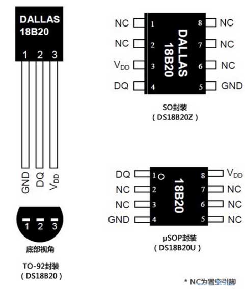
First, let’s get to know the appearance and pin definition of the DS18B20 chip. The common package of the DS18B20 chip is TO-92, which is what an ordinary straight-plug transistor looks like. Of course, you can also find products packaged in SO (DS18B20Z) and μSOP (DS18B20U) forms. The following are illustrations and pin diagrams of various packages of DS18B20.
 After understanding the packaging form of the chip, let’s talk about the definition of each pin. The following table is the pin definition of the chip:
There is a "strange" word mentioned in the above table - "parasitic power supply", so I need to explain it. The DS18B20 chip can operate in "parasitic power mode", which allows the DS18B20 to operate without an external power supply. When the bus is high, parasitic power is supplied from the single bus through the VDD pin. At this time, the DS18B20 can "steal" energy from the bus and store the "stolen" energy in the parasitic power storage capacitor (Cpp). When the bus is low, energy is released for device operation. Therefore, when the DS18B20 operates in parasitic power mode, the VDD pin must be connected to ground.
Part 2: Various circuit connection methods of DS18B20
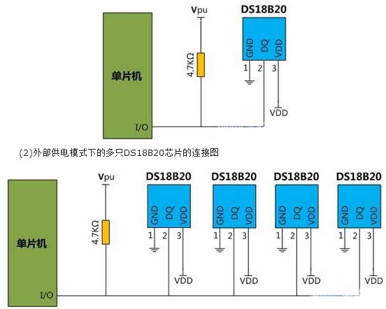
As shown in the two pictures below, they are typical circuit connection diagrams of single and multiple DS18B20 temperature measurement systems in external power supply mode.
 (1) Connection diagram of a single DS18B20 chip in external power supply mode
It should be noted here that the DS18B20 chip relies on a single-wire port for communication through Dallas Company's single-bus protocol. When all devices are connected to the bus via a tri-state port or an open-drain port, the control line needs to be connected to a weak pull-up resistor. When multiple DS18B20s are connected, each DS18B20 has a globally unique 64-bit serial number. In the bus system, the microprocessor relies on the unique 64-bit serial number of each device to identify and record the device address on the bus, allowing multiple DS18B20s to be connected to a single-wire bus at the same time. Therefore, one microprocessor can easily be used to control many DS18B20s distributed in different areas. This feature is very useful in environmental control, detecting the temperature of buildings, instruments, etc., and process monitoring and control.
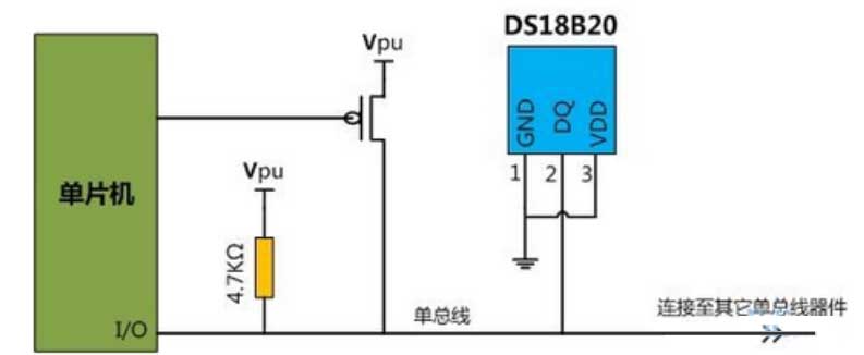
Regarding the circuit connection of DS18B20, in addition to the traditional circuit connection diagram when powered by external power supply mentioned above, DS18B20 can also work in "parasitic power mode". The figure below shows the circuit connection diagram of DS18B20 working in "parasitic power mode". Yes, this allows the DS18B20 to work in parasitic power mode, and can collect temperature information at multiple locations in real time without additional power supplies.
Part 3: DS18B20 internal register analysis and working principle
After introducing the packaging, pin definitions and connection methods of DS18B20, we need to understand the relevant knowledge of each controller and memory of DS18B20 chip. As shown in the figure below, it is the resulting block diagram of the main registers inside the DS18B20.
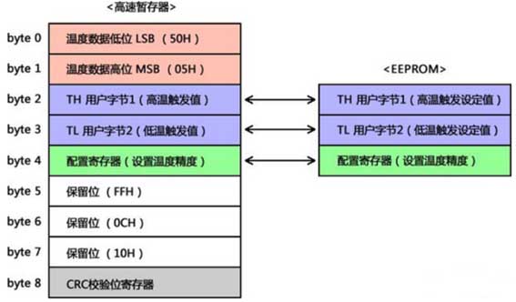 Combined with the internal register block diagram in the figure, let us first briefly talk about the main register workflow of the DS18B20 chip. Before giving a detailed explanation of the working principle of DS18B20, it is necessary to upload a few related pictures:
(1) DS18B20 internal register structure diagram 0
(2) DS18B20 main register data format diagram
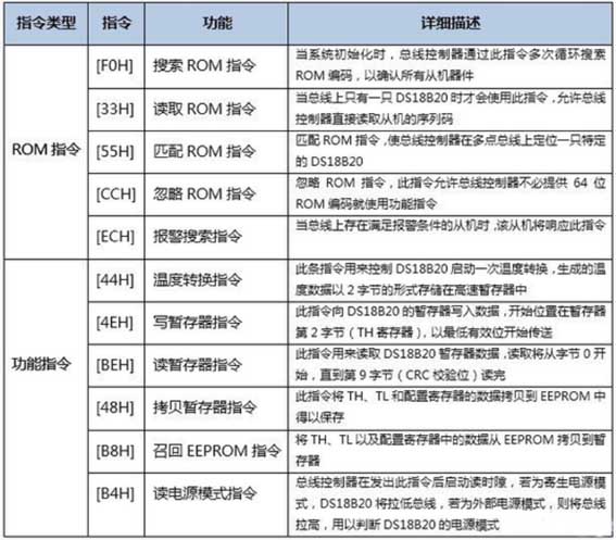
(3) DS18B20 communication command diagram
 Now that we understand these internal structures and details, let’s talk about the working principle of the DS18B20 chip.
DS18B20 will enter the low power consumption waiting state after startup. When temperature measurement and AD conversion need to be performed, the bus controller (mostly a microcontroller) issues the [44H] instruction to complete the temperature measurement and AD conversion (see the above instruction list for other functional instructions). DS18B20 stores the generated temperature data in the temperature register of the high-speed register in the form of two bytes, and then, DS18B20 continues to maintain the waiting state. When the DS18B20 chip is powered by an external power supply, the bus controller initiates a "read time slot" after the temperature conversion command (see the "DS18B20 Time Slot Diagram" of this post for details). Thus, the measured temperature data is read out and the data communication with the microcontroller is completed through the bus. (DS18B20 returns 0 by the DQ pin during temperature conversion, and returns 1 when the conversion is completed. If DS18B20 is powered by a parasitic power supply, unless the bus is entering temperature conversion Pulled high by a strong pull-up, otherwise there will be no return value). In addition, after completing a temperature conversion, DS18B20 will compare the temperature value with the user-defined alarm preset value stored in TH (high temperature trigger) and TL (low temperature trigger), one byte each. The S flag bit in the register (see the "TH and TL register format" diagram in the register format diagram for details) indicates the sign of the temperature value (positive when S=0, negative when S=1). If the measured temperature is higher than TH or lower than TL value, the alarm condition is established, and an alarm flag will be set internally in DS18B20. At this time, the bus controller sends an alarm search command [ECH]. Detect all DS18B20 alarm flags on the bus, and then the DS18B20 that sets the alarm flag will respond to this search command.
First, let’s get to know the appearance and pin definition of the DS18B20 chip. The common package of the DS18B20 chip is TO-92, which is what an ordinary straight-plug transistor looks like. Of course, you can also find products packaged in SO (DS18B20Z) and μSOP (DS18B20U) forms. The following are illustrations and pin diagrams of various packages of DS18B20.
There is a "strange" word mentioned in the above table - "parasitic power supply", so I need to explain it. The DS18B20 chip can operate in "parasitic power mode", which allows the DS18B20 to operate without an external power supply. When the bus is high, parasitic power is supplied from the single bus through the VDD pin. At this time, the DS18B20 can "steal" energy from the bus and store the "stolen" energy in the parasitic power storage capacitor (Cpp). When the bus is low, energy is released for device operation. Therefore, when the DS18B20 operates in parasitic power mode, the VDD pin must be connected to ground.
Part 2: Various circuit connection methods of DS18B20
As shown in the two pictures below, they are typical circuit connection diagrams of single and multiple DS18B20 temperature measurement systems in external power supply mode.
It should be noted here that the DS18B20 chip relies on a single-wire port for communication through Dallas Company's single-bus protocol. When all devices are connected to the bus via a tri-state port or an open-drain port, the control line needs to be connected to a weak pull-up resistor. When multiple DS18B20s are connected, each DS18B20 has a globally unique 64-bit serial number. In the bus system, the microprocessor relies on the unique 64-bit serial number of each device to identify and record the device address on the bus, allowing multiple DS18B20s to be connected to a single-wire bus at the same time. Therefore, one microprocessor can easily be used to control many DS18B20s distributed in different areas. This feature is very useful in environmental control, detecting the temperature of buildings, instruments, etc., and process monitoring and control.
Regarding the circuit connection of DS18B20, in addition to the traditional circuit connection diagram when powered by external power supply mentioned above, DS18B20 can also work in "parasitic power mode". The figure below shows the circuit connection diagram of DS18B20 working in "parasitic power mode". Yes, this allows the DS18B20 to work in parasitic power mode, and can collect temperature information at multiple locations in real time without additional power supplies.
Part 3: DS18B20 internal register analysis and working principle
After introducing the packaging, pin definitions and connection methods of DS18B20, we need to understand the relevant knowledge of each controller and memory of DS18B20 chip. As shown in the figure below, it is the resulting block diagram of the main registers inside the DS18B20.
(1) DS18B20 internal register structure diagram 0
(2) DS18B20 main register data format diagram
(3) DS18B20 communication command diagram
DS18B20 will enter the low power consumption waiting state after startup. When temperature measurement and AD conversion need to be performed, the bus controller (mostly a microcontroller) issues the [44H] instruction to complete the temperature measurement and AD conversion (see the above instruction list for other functional instructions). DS18B20 stores the generated temperature data in the temperature register of the high-speed register in the form of two bytes, and then, DS18B20 continues to maintain the waiting state. When the DS18B20 chip is powered by an external power supply, the bus controller initiates a "read time slot" after the temperature conversion command (see the "DS18B20 Time Slot Diagram" of this post for details). Thus, the measured temperature data is read out and the data communication with the microcontroller is completed through the bus. (DS18B20 returns 0 by the DQ pin during temperature conversion, and returns 1 when the conversion is completed. If DS18B20 is powered by a parasitic power supply, unless the bus is entering temperature conversion Pulled high by a strong pull-up, otherwise there will be no return value). In addition, after completing a temperature conversion, DS18B20 will compare the temperature value with the user-defined alarm preset value stored in TH (high temperature trigger) and TL (low temperature trigger), one byte each. The S flag bit in the register (see the "TH and TL register format" diagram in the register format diagram for details) indicates the sign of the temperature value (positive when S=0, negative when S=1). If the measured temperature is higher than TH or lower than TL value, the alarm condition is established, and an alarm flag will be set internally in DS18B20. At this time, the bus controller sends an alarm search command [ECH]. Detect all DS18B20 alarm flags on the bus, and then the DS18B20 that sets the alarm flag will respond to this search command.


