Temperature Measurement Principle of DS18B20 Sensor
A comprehensive and detailed explanation of the digital temperature sensor DS18B20!
Internal temperature measurement circuit block diagram of DS18B20:
The oscillation frequency of a low temperature coefficient crystal oscillator is very little affected by temperature. It is used to generate a fixed frequency pulse signal and send it to the subtraction counter 1 to provide the counter with a stable frequency counting pulse. The oscillation frequency of high temperature coefficient crystal oscillators changes significantly with temperature changes. A very sensitive oscillator, the signal generated is used as the pulse input of the subtraction counter 2, providing the counter 2 with a counting pulse whose frequency changes with temperature. There are also counting gates implicit in the figure. When the counting gate is opened, the DS18B20 counts the clock pulses generated by the low temperature coefficient oscillator to complete the temperature measurement. The opening time of the counting gate is determined by a high temperature coefficient oscillator. Before each measurement, first put the base number corresponding to -55℃ into the subtraction counter 1 and the temperature register respectively. The subtraction counter 1 and the temperature register are preset at a base value corresponding to -55°C. Subtraction counter 1 performs subtraction counting on the pulse signal generated by the low temperature coefficient crystal oscillator. When the preset value of subtraction counter 1 decreases to 0, the value of the temperature register will be increased by 1, the preset value of subtraction counter 1 will be reloaded, and subtraction counter 1 will restart counting the pulse signals generated by the low temperature coefficient crystal oscillator. This cycle continues until the subtraction counter 2 counts to 0, and the accumulation of the temperature register value stops. At this time, the value in the temperature register is the measured temperature. The slope accumulator is used to compensate and correct the nonlinearity in the temperature measurement process, and its output is used to correct the preset value of the subtraction counter. As long as the counting gate is not closed, the above process is repeated until the temperature register value reaches the measured temperature value.
3. Pin arrangement and packaging diagram of DS18B20
DS18B20 physical pin distribution diagram
DQ is the digital signal input/output terminal; GND is the power ground. VDD is the input terminal of the external power supply, and the power supply is 3.0~5.5V (grounded when the parasitic power supply is connected).
The hardware interface of DS18B20 is very simple. The power supply method is family planning power supply or external power supply.
How parasitic power works
When powered by a parasitic power supply, it is particularly valuable in remote temperature measurements and in situations where measurement space is limited. The principle of parasitic power supply is to "steal" the power of the data line when the data line is high level. Charge is stored on the parasitic supply capacitance and is used to provide power to the device when the data line is low. It should be noted that when the DS18B20 performs temperature conversion or copies the data in the cache to the EEPROM, the required current will reach 1.5mA, which exceeds the current that the capacitor can provide. At this time, a MOSFET transistor can be used to supply power.
External power supply working mode
When DS18B20 uses external power supply, you only need to connect its data line to the one-bit bidirectional port of the microcontroller to realize data transmission.
Note: When the temperature is higher than 100°C, parasitic power cannot be used, because the larger leakage current in the device will make the bus unable to reliably detect high and low levels, resulting in an increase in the bit error rate of data transmission.
Internal temperature measurement circuit block diagram of DS18B20:
The oscillation frequency of a low temperature coefficient crystal oscillator is very little affected by temperature. It is used to generate a fixed frequency pulse signal and send it to the subtraction counter 1 to provide the counter with a stable frequency counting pulse. The oscillation frequency of high temperature coefficient crystal oscillators changes significantly with temperature changes. A very sensitive oscillator, the signal generated is used as the pulse input of the subtraction counter 2, providing the counter 2 with a counting pulse whose frequency changes with temperature. There are also counting gates implicit in the figure. When the counting gate is opened, the DS18B20 counts the clock pulses generated by the low temperature coefficient oscillator to complete the temperature measurement. The opening time of the counting gate is determined by a high temperature coefficient oscillator. Before each measurement, first put the base number corresponding to -55℃ into the subtraction counter 1 and the temperature register respectively. The subtraction counter 1 and the temperature register are preset at a base value corresponding to -55°C. Subtraction counter 1 performs subtraction counting on the pulse signal generated by the low temperature coefficient crystal oscillator. When the preset value of subtraction counter 1 decreases to 0, the value of the temperature register will be increased by 1, the preset value of subtraction counter 1 will be reloaded, and subtraction counter 1 will restart counting the pulse signals generated by the low temperature coefficient crystal oscillator. This cycle continues until the subtraction counter 2 counts to 0, and the accumulation of the temperature register value stops. At this time, the value in the temperature register is the measured temperature. The slope accumulator is used to compensate and correct the nonlinearity in the temperature measurement process, and its output is used to correct the preset value of the subtraction counter. As long as the counting gate is not closed, the above process is repeated until the temperature register value reaches the measured temperature value.
 |
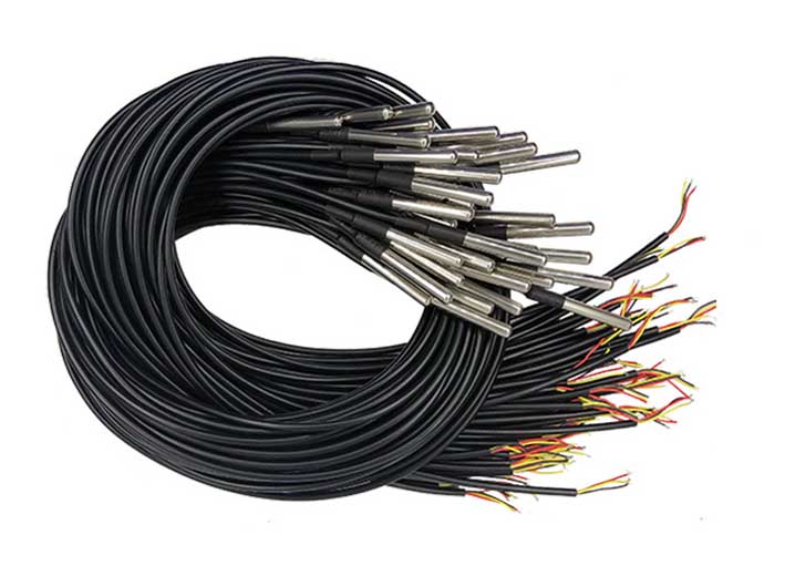 |
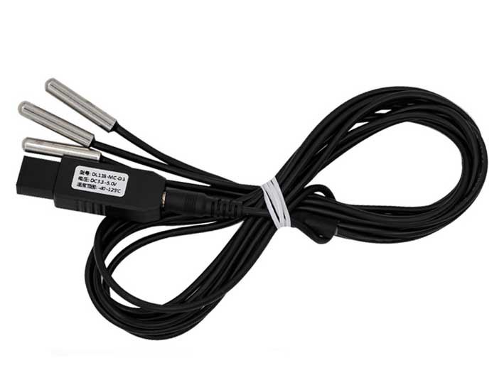
| DS18B20 acquisition temperature sensor with USB interface | 1 meter/1 wire ds18b20 digital temperature sensor |
3. Pin arrangement and packaging diagram of DS18B20
DS18B20 physical pin distribution diagram
DQ is the digital signal input/output terminal; GND is the power ground. VDD is the input terminal of the external power supply, and the power supply is 3.0~5.5V (grounded when the parasitic power supply is connected).
The hardware interface of DS18B20 is very simple. The power supply method is family planning power supply or external power supply.
How parasitic power works
When powered by a parasitic power supply, it is particularly valuable in remote temperature measurements and in situations where measurement space is limited. The principle of parasitic power supply is to "steal" the power of the data line when the data line is high level. Charge is stored on the parasitic supply capacitance and is used to provide power to the device when the data line is low. It should be noted that when the DS18B20 performs temperature conversion or copies the data in the cache to the EEPROM, the required current will reach 1.5mA, which exceeds the current that the capacitor can provide. At this time, a MOSFET transistor can be used to supply power.
External power supply working mode
When DS18B20 uses external power supply, you only need to connect its data line to the one-bit bidirectional port of the microcontroller to realize data transmission.
Note: When the temperature is higher than 100°C, parasitic power cannot be used, because the larger leakage current in the device will make the bus unable to reliably detect high and low levels, resulting in an increase in the bit error rate of data transmission.


