Trouble analysis and elimination of thermocouple

Judgement method of thermocouple input failure:
After the thermocouple is correctly wired according to the meter wiring diagram, the meter first displays the thermocouple index number of the meter. Then display the range of the meter, and then measure the lower row of the meter to display the set temperature, and the upper row of the meter to display the measured temperature. The above process shows the correct use of thermocouples. If the display on the top of the meter is not the temperature of the heating element, it will display “OVER”, “0000” or “000”. Explain that the input part of the instrument has a failure, and the following tests should be done:1) Remove the thermocouple from the input terminal of the instrument thermocouple, and then use any wire to short-circuit the input terminal of the instrument thermocouple. When the power is on, when the display value of the digital tube on the meter is about room temperature, it means that the internal wiring of the thermocouple is open, and the thermocouple of the same type should be replaced. If it is still in the above-mentioned condition, it means that the input terminal of the instrument was damaged during transportation, and the instrument should be replaced.
2) Remove the thermocouple of the above-mentioned malfunctioning instrument, and replace it with the thermocouple connected to the instrument with the same kind of indexing number that is running normally next to it. After power on, when the digital tube on the original faulty meter displays the temperature of the heating element, it means that the thermocouple connection is open. Replace the same type of thermocouple.
3) Remove the faulty thermocouple from the meter, place the multimeter in the measurement ohm (R) *1 file, and use the two meter rods of the multimeter to measure the two ends of the thermocouple. If the resistance value displayed on the multimeter is very large, it means that the internal connection of the thermocouple is open. Replace the thermocouple of the same type. Otherwise, there is a certain resistance value, indicating that there is a problem with the input end of the meter, and the meter should be replaced.
4) The wiring is correct according to the wiring diagram of the meter. If the meter is powered on, the digital display on the meter will display a negative value, etc. Explain that the thermocouple "+" and "—" connected to the instrument are connected incorrectly. Just change it again.
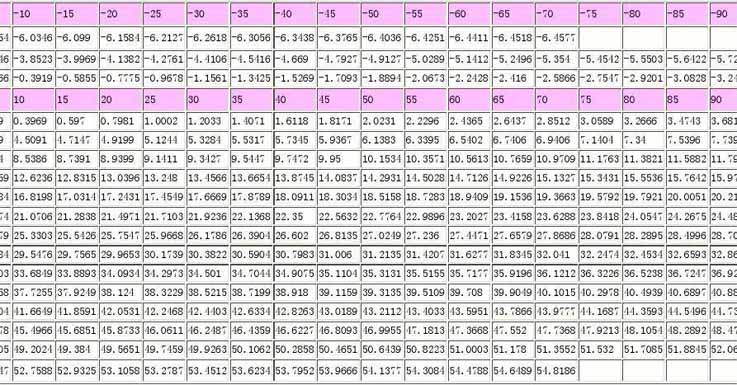
5) When the meter is running after the wiring is correct, the temperature displayed by the digital display on the meter differs from the actual measured temperature by 40°C to 70°C. The difference is even greater, indicating that the graduation number of the meter and the graduation number of the thermocouple are wrong. According to the thermocouple index number B, S, K, E and other thermocouple temperature and millivolt (MV) value of the corresponding relationship. At the same temperature, the generated millivolt value (MV) B index number is the smallest, S index number is the smallest, K index number is larger, and E index number is the largest. According to this principle to judge.
Analysis and treatment of common failures:
|
Failure phenomenon
|
Possible Causes
|
Solution
|
|
The thermoelectric potential is smaller than the actual value (the indicated value of the display instrument is lower)
|
Hot electrode short circuit
|
If it is wet, dry it; If the insulator is damaged, replace the insulator
|
|
Dust builds up at the thermocouple terminal, causing a short circuit
|
Clean up dust
|
|
|
Short circuit between compensation wires
|
Find the short-circuit point, strengthen the insulation or replace the compensating wire
|
|
|
Deterioration of thermocouple thermoelectrode
|
When the length allows, cut off the deteriorated section and re-weld, or replace with a new thermocouple
|
|
|
Reverse polarity of compensation wire and thermocouple
|
Reconnect correctly
|
|
|
Compensation wire does not match the thermocouple
|
Replace the matching compensation wire
|
|
|
The thermocouple installation position is not recorded or the insertion depth does not meet the requirements
|
Reinstall as required
|
|
|
Thermocouple cold junction temperature compensation does not meet the requirements
|
Adjust the cold junction compensator
|
|
|
The thermocouple is not matched with the display instrument
|
Replace thermocouple or display instrument to match
|
|
|
The thermoelectric potential is larger than the actual value (the indication value of the display instrument is higher)
|
The display instrument is not matched with the thermocouple
|
Replace the thermocouple to match it
|
|
Thermocouple and compensation wire do not match
|
Replace the compensation wire to match it
|
|
|
DC interference signal enters
|
Eliminate DC interference
|
|
|
Unstable thermoelectric power output
|
Poor contact between thermocouple terminal and hot electrode
|
Tighten the terminal screws
|
|
The insulation of the thermocouple measuring circuit is damaged, causing intermittent short circuit or grounding
|
Find the fault point and repair the insulation
|
|
|
Insufficient installation of thermocouple or external vibration
|
Tighten the thermocouple to eliminate vibration or take shock absorption measures
|
|
|
The hot electrode will break unbroken
|
Repair or replace thermocouple
|
|
|
External interference (AC leakage, electromagnetic field induction, etc.)
|
Detect the source of interference and adopt shielding measures
|
|
|
Large thermocouple thermoelectric potential error
|
Deterioration of thermoelectrode
|
Replace the hot electrode
|
|
Improper installation position of thermocouple
|
Change the installation location
|
|
|
Protection tube surface dust
|
Remove dust accumulation
|