How to use thermocouple correctly?
The correct use of thermocouples can not only accurately obtain the value of the temperature and ensure that the product is qualified, but also save the material consumption of the thermocouple, which saves money and ensures accurate detection. Incorrect installation, thermal conductivity and time lag errors are the main errors in the use of thermocouples.
In order to accurately measure the temperature, a thermocouple with a small time constant should be selected. The time constant is inversely proportional to the heat transfer coefficient, and directly proportional to the diameter of the hot end of the thermocouple, the density of the material, and the specific heat. To reduce the time constant, in addition to increasing the heat transfer coefficient, the most effective way is to minimize the size of the hot end. In use, materials with good thermal conductivity are usually used, and protective sleeves with thin tube walls and small inner diameters are used. In more precise temperature measurement, a bare-wire thermocouple without protective sleeve is used, but the thermocouple is easily damaged and should be corrected and replaced in time.
1. Errors caused by improper installation of thermocouples
For example, the installation position and insertion depth of the thermocouple cannot reflect the true temperature of the furnace. In other words, the thermocouple should not be installed too close to the interface and heating position, and the depth of insertion should be at least 8-10 times the diameter of the protective tube; The gap between the thermocouple's protective tube and the wall is not filled with insulating material, causing heat overflow or cold air intrusion in the furnace. Therefore, the gap between the thermocouple protection tube and the furnace wall hole should be blocked with refractory mud or asbestos rope to prevent the convection of cold and hot air from affecting the accuracy of temperature measurement; The cold end of the thermocouple is too close to the furnace body and the temperature exceeds 100℃; The installation of thermocouples should avoid strong magnetic fields and strong electric fields as much as possible, so thermocouples and power cables should not be installed in the same conduit to avoid introducing interference and causing errors; The thermocouple cannot be installed in an area where the measured medium seldom flows. When using a thermocouple to measure the temperature of the gas in the tube, the thermocouple must be installed against the direction of the flow rate and fully in contact with the gas.2. Errors caused by the deterioration of the insulation of the thermocouple
Such as the thermocouple insulation layer, protection tube, pull wire plate dirt or salt slag too much, resulting in poor insulation between the thermocouple pole and the furnace wall, the error is more serious at high temperatures. This not only causes the loss of thermoelectric potential but also introduces interference, and the error caused by this can sometimes reach 100°C.3. Errors caused by the thermal inertia of the thermocouple
Due to the thermal inertia of the thermocouple, the indicator value of the meter lags behind the change of the measured temperature, and this effect is particularly prominent during rapid measurement. Therefore, thermocouples with thinner thermoelectrodes and smaller protective tube diameters should be used as much as possible. The protective tube can even be removed when the temperature measurement environment permits. Due to the measurement lag, the amplitude of the temperature fluctuation detected by the thermocouple is smaller than the amplitude of the furnace temperature fluctuation. The greater the measurement lag, the smaller the amplitude of thermocouple fluctuations, and the greater the difference from the actual furnace temperature. When a thermocouple with a large time constant is used for temperature measurement or temperature control, although the temperature displayed by the meter fluctuates very little, the actual furnace temperature may fluctuate greatly.In order to accurately measure the temperature, a thermocouple with a small time constant should be selected. The time constant is inversely proportional to the heat transfer coefficient, and directly proportional to the diameter of the hot end of the thermocouple, the density of the material, and the specific heat. To reduce the time constant, in addition to increasing the heat transfer coefficient, the most effective way is to minimize the size of the hot end. In use, materials with good thermal conductivity are usually used, and protective sleeves with thin tube walls and small inner diameters are used. In more precise temperature measurement, a bare-wire thermocouple without protective sleeve is used, but the thermocouple is easily damaged and should be corrected and replaced in time.
4. Thermal resistance error of thermocouple
At high temperatures, if there is a layer of soot on the protective tube and dust is attached to it, the thermal resistance will increase and hinder the heat conduction. At this time, the temperature indication is lower than the true value of the measured temperature. Therefore, the outside of the thermocouple protection tube should be kept clean to reduce errors.Temperature compensation of thermocouple
Since the materials of thermocouples are generally more expensive (especially when precious metals are used), the distance between the temperature measurement point and the meter is very long. In order to save thermocouple materials and reduce costs, compensation wires are usually used to extend the cold end (free end) of the thermocouple into the control room where the temperature is relatively stable, and connect it to the instrument terminal. It must be pointed out that the function of the thermocouple compensation wire is only to extend the thermoelectrode and move the cold end of the thermocouple to the instrument terminal in the control room. It cannot eliminate the influence of the temperature change of the cold junction on the temperature measurement by itself, and cannot compensate. Therefore, other correction methods are needed to compensate for the influence of the cold junction temperature t0≠0°C on the temperature measurement. When using the thermocouple compensation wire, you must pay attention to the matching of the model, the polarity can not be wrong, and the temperature difference between the compensation wire and the thermocouple connection end can not exceed 100 ℃.
 |
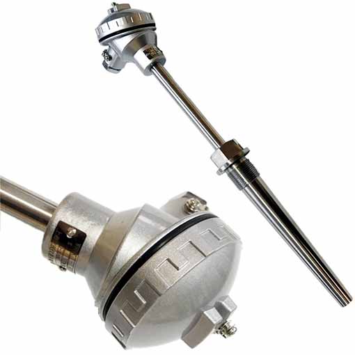 |
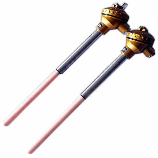
| R type 0-1600℃ corundum tube thermocouple | Quick test thermocouple |
 |
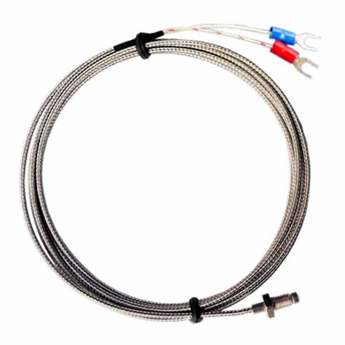 |
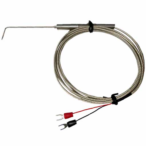
| Thermal inertia of probe thermocouple | Shielded wire thermocouple, electric heating rod |


