Experience using DS18B20 Chip Digital Sensor
(1) Experience in using DS18B20 chip digital temperature sensors with TH (high temperature trigger register) and TL (low temperature trigger register).
For TH (high temperature trigger register) and TL (low temperature trigger register) in DS18B20, there is very little code information that can be found. And if you need to use the TH and TL registers in a certain temperature measurement system, you don't have to feel that you don't know where to start. See "DS18B20 Register Structure" in this post. The bus controller's read operation will gradually read data downwards starting from bit 0 until bit 8 is read. Moreover, the internal structure and data format of the TH and TL registers are the same as other registers on the chip. Of course, reading and writing the TH and TL registers are the same as reading and writing other on-chip registers. Therefore, in practical applications, when the initialization of DS18B20 is completed, the data saved in the EEPROM is first recalled to the TH and TL of the temporary register through the [B8H] instruction issued by the bus controller. Then the device temporary register is read through the "read time slot" issued by the bus controller. As long as every 8-bit data read is obtained in time, the TH and TL register data can be easily read through the bus controller. The same principle applies to the bus controller's write operation to the device. In other words, as long as you master the operation programming of other registers, you can easily read and write the two alarm value registers TH and TL. At the same time, the TH and TL register data can be copied to EEPROM for storage through the [48H] instruction.
(2) Experience in mastering DS18B20 communication time slots
In the temperature detection system built by the DS18B20 chip, Dallas Company's unique single-bus data communication method is used, allowing multiple DS18B20s to be mounted on one bus. Then, in the operation and control of DS18B20, the time slot signal sent by the bus controller is particularly important. As shown in the figure below, they are the schematic diagrams of the power-on initialization time slot of the DS18B20 chip, the bus controller reading data time slot from DS18B20, and the bus controller writing data time slot to DS18B20. When programming the system, you must strictly refer to the time data in the time slot diagram to accurately grasp the changes in the bus level with time (microsecond level), so that you can control and operate the DS18B20 smoothly. In addition, it should be noted that the machine cycles of different microcontrollers are different, so the delay function in the program is not exactly the same and must be changed according to the different machine cycles of the microcontroller. In normal DS18B20 program debugging, if faults such as temperature display errors are found, it is basically caused by large time slot errors or even time slot errors. Special care is required when programming the DS18B20.
 Power-on initialization time slot diagram
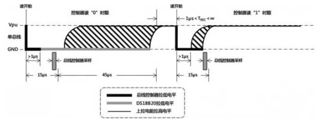 Time slot diagram of the communication bus when reading data
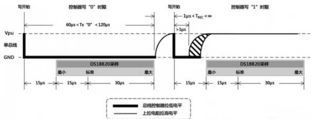
 Time slot diagram of communication bus when data is written
Okay, this post is basically coming to an end. We describe the packaging, pin definitions, circuit connection methods, internal register structure and data format, communication time slots and function/control instructions of the DS18B20 temperature measurement chip. Finally, I hope this post can help friends who are or will use the DS18B20 temperature measurement chip. Thank you all!
For TH (high temperature trigger register) and TL (low temperature trigger register) in DS18B20, there is very little code information that can be found. And if you need to use the TH and TL registers in a certain temperature measurement system, you don't have to feel that you don't know where to start. See "DS18B20 Register Structure" in this post. The bus controller's read operation will gradually read data downwards starting from bit 0 until bit 8 is read. Moreover, the internal structure and data format of the TH and TL registers are the same as other registers on the chip. Of course, reading and writing the TH and TL registers are the same as reading and writing other on-chip registers. Therefore, in practical applications, when the initialization of DS18B20 is completed, the data saved in the EEPROM is first recalled to the TH and TL of the temporary register through the [B8H] instruction issued by the bus controller. Then the device temporary register is read through the "read time slot" issued by the bus controller. As long as every 8-bit data read is obtained in time, the TH and TL register data can be easily read through the bus controller. The same principle applies to the bus controller's write operation to the device. In other words, as long as you master the operation programming of other registers, you can easily read and write the two alarm value registers TH and TL. At the same time, the TH and TL register data can be copied to EEPROM for storage through the [48H] instruction.
(2) Experience in mastering DS18B20 communication time slots
In the temperature detection system built by the DS18B20 chip, Dallas Company's unique single-bus data communication method is used, allowing multiple DS18B20s to be mounted on one bus. Then, in the operation and control of DS18B20, the time slot signal sent by the bus controller is particularly important. As shown in the figure below, they are the schematic diagrams of the power-on initialization time slot of the DS18B20 chip, the bus controller reading data time slot from DS18B20, and the bus controller writing data time slot to DS18B20. When programming the system, you must strictly refer to the time data in the time slot diagram to accurately grasp the changes in the bus level with time (microsecond level), so that you can control and operate the DS18B20 smoothly. In addition, it should be noted that the machine cycles of different microcontrollers are different, so the delay function in the program is not exactly the same and must be changed according to the different machine cycles of the microcontroller. In normal DS18B20 program debugging, if faults such as temperature display errors are found, it is basically caused by large time slot errors or even time slot errors. Special care is required when programming the DS18B20.
Okay, this post is basically coming to an end. We describe the packaging, pin definitions, circuit connection methods, internal register structure and data format, communication time slots and function/control instructions of the DS18B20 temperature measurement chip. Finally, I hope this post can help friends who are or will use the DS18B20 temperature measurement chip. Thank you all!


