Design of Antenna in SAW Temperature Sensor Temperature Measurement System
In many power equipments, due to the installation process and aging, etc., the contact resistance of the power line contacts becomes large, which in turn causes the temperature to rise, and in severe cases, the contacts are blown, causing power failure. In order to avoid this safety hazard, it is necessary to design and develop a temperature monitoring device.
Conventional temperature sensors cannot perform continuous temperature monitoring in harsh environments such as high voltage and high current, while surface acoustic wave temperature sensors can be combined with antenna systems to achieve wireless passive detection and operate normally in the above-mentioned harsh environments. Lee Keekeun and FACHBERGER R et al. designed a delayed linear surface acoustic wave temperature sensor. One center frequency is 440 MHz and the other is 2.4 GHz, which can be used for temperature detection in high temperature environments, but the maximum effective detection distance between the two is not far. Ling Mingfang and Zhu Yunhai designed the circuit of the surface acoustic wave resonator type temperature sensor. The test data shows: The surface acoustic wave resonance type temperature sensor has the advantages of high frequency stability and good linearity, and is suitable for testing in high-precision temperature applications. According to the research status at home and abroad, the resonant surface acoustic wave temperature sensor can be summarized, which has the advantages of good reliability and high sensitivity. Compared with the delay line type, it is more suitable for wireless detection.
Planar inverted F antenna, ie PIFA antenna.
It has the advantages of being unaffected by the metal body, easy to integrate, and has its own reference plane. As the system transmitting antenna, it is connected with the reader and is responsible for transmitting the excitation signal and receiving the reflected signal. The normal mode spiral is used as the receiving antenna of the system because of its small size and radiation omnidirectional radiation. It is responsible for receiving the signal from the transmitting antenna and transmitting it to the surface acoustic wave temperature transmitter. Therefore, the transmitting antenna of the system is PIFA, and the receiving antenna is a normal mode helical antenna.
1 system overall design
SAW (Surface Acoustic Wave) temperature sensor uses surface acoustic wave technology. Compared with traditional sensors, it has the advantages of high precision, high sensitivity, easy integration, and low power consumption. The most prominent is that it can work continuously in the harsh environment of high voltage and high current.
SAW sensors can be roughly divided into 4 types: Active delay line type, active resonance type, passive delay line type and passive resonance type. The passive resonant SAW sensor used in this system has the advantages of passiveness and high sensitivity compared with other types, and is more suitable for wireless temperature detection. The overall design of the system is shown in Figure 1.
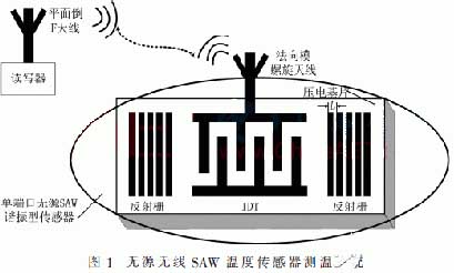
working principle: The reader generates an excitation signal, and the PIFA antenna receives and transmits the excitation signal. The normal mode helical antenna uses the received signal to drive the SAW temperature sensor, and its interdigital transducer converts the received electrical signal into an acoustic signal. When the temperature on the piezoelectric substrate of the SAW sensor changes, the propagation speed of the surface acoustic wave changes, thereby changing the resonant frequency of the SAW sensor. The acoustic signal passes back to the interdigital transducer after passing through the reflective grid. The interdigital transducer converts it into an electrical signal, and the signal with temperature information is fed back to the reader through the normal mode helical antenna. Finally, the reader obtains the temperature value by comparing the changes of the two signal frequencies and combining the relationship between frequency and temperature.
2 PIFA antenna design
2.1 Model design
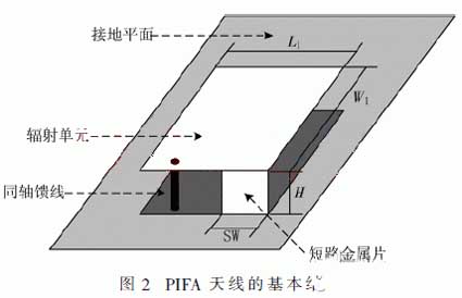
A typical PIFA antenna is used as the signal receiving and radiating unit of the sensor, and its basic structure is shown in FIG 2. The PIFA antenna mainly includes a ground plane, a radiating element, a short-circuited metal piece and a coaxial feed line, and L1 and W1 are respectively the length and width of the radiating element. SW and H are the width and height of the shorted metal piece, respectively.
(1) Design of the radiation unit
The relationship between the length L1 of the radiating element of the PIFA antenna and the width W1 is related to the central operating wavelength λc:

The center of the antenna in this system operates at 915 MHz, so the value of λc is approximately 327.87 mm. According to the formula (1), the values of L1 and W1 are obtained. In the original model of this design, L1 was 55 mm and W1 was 32 mm.
(2) Design of short circuit metal piece
The width SW of the shorted metal piece has an effect on the resonant frequency and effective bandwidth of the antenna. In this design, the initial model SW has a value of 5 mm.
(3) Design of Feed Point
In this design, the feed mode uses coaxial feed. The coordinates of the center of the same axis are (Xf, Yf, 0), the inner diameter is represented by r1, and the outer diameter is represented by r2. The values of Xf and Yf are 16 mm and 5 mm, respectively, and the values of r1 and r2 are 0.25 mm and 0.59 mm, respectively.
(4) Design of Grounding Plane
2.2 Analysis of simulation results
Through simulation, the sweep result of the return loss S11 is obtained, and the center operating frequency (resonance frequency) of the PIFA antenna can be obtained as 915 MHz. The 10 dB bandwidth is approximately 101 MHz (872.1 MHz to 973.5 MHz) and is greater than 80 MHz to meet the requirements of this design.
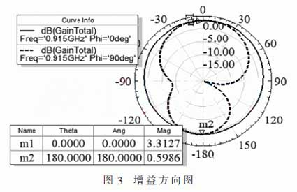
Figure 3 is a gain diagram of the PIFA antenna on the xz and yz cross sections. Radiating surface is defined based on spherical coordinates, so = 0 ° plane of the xz plane, a solid line is a gain pattern on the xz cross section; The plane of =90° is the yz plane, and the dashed line in the figure is the gain pattern on the yz section. M1 is the maximum gain point, directly above the radiating element, with a gain of 3.34 dB and a gain of m2 of approximately 0.55 dB.
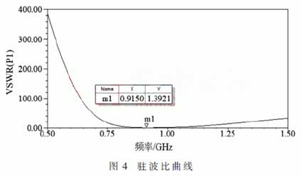
The standing wave ratio curve of the PIFA antenna is shown in Fig 4. The m1 point in the figure indicates that when the PIFA antenna operates at a center frequency of 915 MHz, the standing wave ratio is about 1.24 and less than 1.5, indicating that the working state of the PIFA is close to the traveling wave at this time, and the transmission characteristics are ideal, which is in accordance with the design goal.
 2.3 Optimization design
In order to get the optimal antenna structure size, the main parameters of the antenna are simulated and optimized.
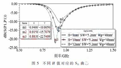
(1) Effect of antenna height on operating frequency and bandwidth
The antenna height is indicated by the variable H. It can be seen from the points m1, m2, and m3 in Fig. 5 that the resonance frequencies are 940 MHz, 915 MHz, and 883 MHz when the H values are 8 mm, 10 mm, and 12 mm. At the same time, the corresponding 10 dB bandwidths are 44 MHz, 101.4 MHz and 105.4 MHz. It can be concluded that as the H increases, the operating frequency of the PIFA antenna gradually decreases, and the bandwidth gradually becomes larger. In practical applications, the height of H is generally prohibited below 6 mm, not higher than 12 mm. In this design, H is chosen to be 10 mm.
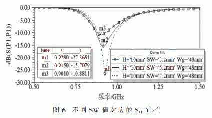
(2) Effect of short-circuit metal strip width on operating frequency and bandwidth
The variable SW is used to indicate the width of the shorted metal piece of the PIFA antenna. It can be seen from m1, m2, and m3 in Fig. 6. When the SW is 7.2 mm, 5.2 mm, and 3.2 mm, the corresponding resonant frequencies are 901 MHz, 915 MHz, and 928 MHz. The corresponding 10 dB bandwidths are 111.8 MHz, 101.4 MHz, and 53.3 MHz, respectively. Therefore, the smaller the width of the short-circuited metal piece while keeping other parameters constant, the lower the center operating frequency of the PIFA antenna and the narrower the bandwidth.
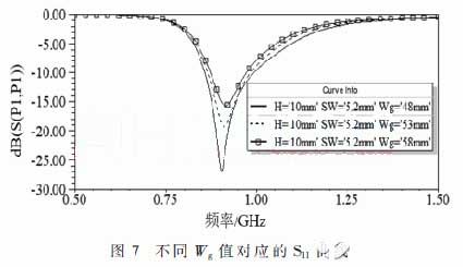
(3) The effect of the width of the ground plane on the operating frequency and bandwidth
The variable Wg is used to indicate the width of the PIFA antenna ground plane. Figure 7 shows the results of the parameter sweep analysis. It can be seen that as the width Wg of the ground plane increases, the resonant frequency of the PIFA antenna hardly changes, but the bandwidth changes significantly. That is, when the other constants are maintained, the bandwidth of the PIFA antenna gradually decreases as the Wg changes from 48 mm to 58 mm.
(4) Impedance matching of PIFA antenna
There are many methods for impedance matching, which can adjust the antenna structure or size, and can also increase the matching network. Since the position of the feed point of the PIFA antenna greatly affects the input impedance, impedance matching is performed by changing the position of the feed point. It mainly changes the value of W1 to change the x-axis center coordinate Xf (Xf=W1/2) of coaxial feeder. According to the simulation results, it is necessary to fine-tune the y-axis center coordinate Yf and other dimensions of coaxial feeder in order to achieve the desired goal. After matching, the PIFA antenna has an input impedance of (50-j 10) Ω at a center operating frequency of 915 MHz, which meets the design requirements.
Conventional temperature sensors cannot perform continuous temperature monitoring in harsh environments such as high voltage and high current, while surface acoustic wave temperature sensors can be combined with antenna systems to achieve wireless passive detection and operate normally in the above-mentioned harsh environments. Lee Keekeun and FACHBERGER R et al. designed a delayed linear surface acoustic wave temperature sensor. One center frequency is 440 MHz and the other is 2.4 GHz, which can be used for temperature detection in high temperature environments, but the maximum effective detection distance between the two is not far. Ling Mingfang and Zhu Yunhai designed the circuit of the surface acoustic wave resonator type temperature sensor. The test data shows: The surface acoustic wave resonance type temperature sensor has the advantages of high frequency stability and good linearity, and is suitable for testing in high-precision temperature applications. According to the research status at home and abroad, the resonant surface acoustic wave temperature sensor can be summarized, which has the advantages of good reliability and high sensitivity. Compared with the delay line type, it is more suitable for wireless detection.
Planar inverted F antenna, ie PIFA antenna.
It has the advantages of being unaffected by the metal body, easy to integrate, and has its own reference plane. As the system transmitting antenna, it is connected with the reader and is responsible for transmitting the excitation signal and receiving the reflected signal. The normal mode spiral is used as the receiving antenna of the system because of its small size and radiation omnidirectional radiation. It is responsible for receiving the signal from the transmitting antenna and transmitting it to the surface acoustic wave temperature transmitter. Therefore, the transmitting antenna of the system is PIFA, and the receiving antenna is a normal mode helical antenna.
1 system overall design
SAW (Surface Acoustic Wave) temperature sensor uses surface acoustic wave technology. Compared with traditional sensors, it has the advantages of high precision, high sensitivity, easy integration, and low power consumption. The most prominent is that it can work continuously in the harsh environment of high voltage and high current.
SAW sensors can be roughly divided into 4 types: Active delay line type, active resonance type, passive delay line type and passive resonance type. The passive resonant SAW sensor used in this system has the advantages of passiveness and high sensitivity compared with other types, and is more suitable for wireless temperature detection. The overall design of the system is shown in Figure 1.
working principle: The reader generates an excitation signal, and the PIFA antenna receives and transmits the excitation signal. The normal mode helical antenna uses the received signal to drive the SAW temperature sensor, and its interdigital transducer converts the received electrical signal into an acoustic signal. When the temperature on the piezoelectric substrate of the SAW sensor changes, the propagation speed of the surface acoustic wave changes, thereby changing the resonant frequency of the SAW sensor. The acoustic signal passes back to the interdigital transducer after passing through the reflective grid. The interdigital transducer converts it into an electrical signal, and the signal with temperature information is fed back to the reader through the normal mode helical antenna. Finally, the reader obtains the temperature value by comparing the changes of the two signal frequencies and combining the relationship between frequency and temperature.
2 PIFA antenna design
2.1 Model design
A typical PIFA antenna is used as the signal receiving and radiating unit of the sensor, and its basic structure is shown in FIG 2. The PIFA antenna mainly includes a ground plane, a radiating element, a short-circuited metal piece and a coaxial feed line, and L1 and W1 are respectively the length and width of the radiating element. SW and H are the width and height of the shorted metal piece, respectively.
(1) Design of the radiation unit
The relationship between the length L1 of the radiating element of the PIFA antenna and the width W1 is related to the central operating wavelength λc:
The center of the antenna in this system operates at 915 MHz, so the value of λc is approximately 327.87 mm. According to the formula (1), the values of L1 and W1 are obtained. In the original model of this design, L1 was 55 mm and W1 was 32 mm.
(2) Design of short circuit metal piece
The width SW of the shorted metal piece has an effect on the resonant frequency and effective bandwidth of the antenna. In this design, the initial model SW has a value of 5 mm.
(3) Design of Feed Point
In this design, the feed mode uses coaxial feed. The coordinates of the center of the same axis are (Xf, Yf, 0), the inner diameter is represented by r1, and the outer diameter is represented by r2. The values of Xf and Yf are 16 mm and 5 mm, respectively, and the values of r1 and r2 are 0.25 mm and 0.59 mm, respectively.
(4) Design of Grounding Plane
2.2 Analysis of simulation results
Through simulation, the sweep result of the return loss S11 is obtained, and the center operating frequency (resonance frequency) of the PIFA antenna can be obtained as 915 MHz. The 10 dB bandwidth is approximately 101 MHz (872.1 MHz to 973.5 MHz) and is greater than 80 MHz to meet the requirements of this design.
Figure 3 is a gain diagram of the PIFA antenna on the xz and yz cross sections. Radiating surface is defined based on spherical coordinates, so
= 0 ° plane of the xz plane, a solid line is a gain pattern on the xz cross section; The plane of =90° is the yz plane, and the dashed line in the figure is the gain pattern on the yz section. M1 is the maximum gain point, directly above the radiating element, with a gain of 3.34 dB and a gain of m2 of approximately 0.55 dB.
The standing wave ratio curve of the PIFA antenna is shown in Fig 4. The m1 point in the figure indicates that when the PIFA antenna operates at a center frequency of 915 MHz, the standing wave ratio is about 1.24 and less than 1.5, indicating that the working state of the PIFA is close to the traveling wave at this time, and the transmission characteristics are ideal, which is in accordance with the design goal.
In order to get the optimal antenna structure size, the main parameters of the antenna are simulated and optimized.
(1) Effect of antenna height on operating frequency and bandwidth
The antenna height is indicated by the variable H. It can be seen from the points m1, m2, and m3 in Fig. 5 that the resonance frequencies are 940 MHz, 915 MHz, and 883 MHz when the H values are 8 mm, 10 mm, and 12 mm. At the same time, the corresponding 10 dB bandwidths are 44 MHz, 101.4 MHz and 105.4 MHz. It can be concluded that as the H increases, the operating frequency of the PIFA antenna gradually decreases, and the bandwidth gradually becomes larger. In practical applications, the height of H is generally prohibited below 6 mm, not higher than 12 mm. In this design, H is chosen to be 10 mm.
(2) Effect of short-circuit metal strip width on operating frequency and bandwidth
The variable SW is used to indicate the width of the shorted metal piece of the PIFA antenna. It can be seen from m1, m2, and m3 in Fig. 6. When the SW is 7.2 mm, 5.2 mm, and 3.2 mm, the corresponding resonant frequencies are 901 MHz, 915 MHz, and 928 MHz. The corresponding 10 dB bandwidths are 111.8 MHz, 101.4 MHz, and 53.3 MHz, respectively. Therefore, the smaller the width of the short-circuited metal piece while keeping other parameters constant, the lower the center operating frequency of the PIFA antenna and the narrower the bandwidth.
(3) The effect of the width of the ground plane on the operating frequency and bandwidth
The variable Wg is used to indicate the width of the PIFA antenna ground plane. Figure 7 shows the results of the parameter sweep analysis. It can be seen that as the width Wg of the ground plane increases, the resonant frequency of the PIFA antenna hardly changes, but the bandwidth changes significantly. That is, when the other constants are maintained, the bandwidth of the PIFA antenna gradually decreases as the Wg changes from 48 mm to 58 mm.
(4) Impedance matching of PIFA antenna
There are many methods for impedance matching, which can adjust the antenna structure or size, and can also increase the matching network. Since the position of the feed point of the PIFA antenna greatly affects the input impedance, impedance matching is performed by changing the position of the feed point. It mainly changes the value of W1 to change the x-axis center coordinate Xf (Xf=W1/2) of coaxial feeder. According to the simulation results, it is necessary to fine-tune the y-axis center coordinate Yf and other dimensions of coaxial feeder in order to achieve the desired goal. After matching, the PIFA antenna has an input impedance of (50-j 10) Ω at a center operating frequency of 915 MHz, which meets the design requirements.


