Wiring Method of PT100 Sensor Harness
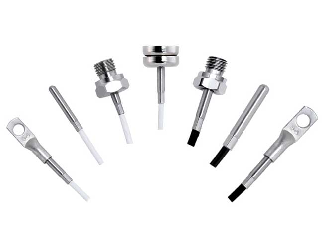
The installation wiring harness of the sensor pt100 can be equipped with patch type, magnet, screw, or threaded plug-in connectors. PT100 temperature sensor, M6 thread, shielded temperature measurement wire probe, K-type, S-type armored thermocouple wire harness.
The main technical parameters of the Pt100 temperature sensor wire harness are as follows:
Measuring range: -200℃~+850℃; allowable deviation value △℃: A level ± (0.15+0.002│t│), B level ± (0.30+0.005│t│). Thermal response time current ≤5mA. In addition, the Pt100 temperature sensor also has the advantages of anti-vibration, good stability, high accuracy, and high pressure resistance.
Pt100 means that its resistance is 100 ohms at 0 degrees. PT100 temperature is a resistive temperature sensor made of platinum (Pt) and has a positive resistance coefficient. The relationship between resistance and temperature change is as follows: R=Ro(1+αT).
 3. Connection method of three core wires of PT100 temperature sensor
1. The PT100 platinum resistance sensor has three leads, and A, B, and C (or black, red, and yellow) can be used to represent the three wires. The following rules exist between the three wires: the resistance between A and B or C is about 110 ohms at room temperature, and the resistance between B and C is 0 ohms. B and C are directly connected internally. In principle, there is no difference between B and C.
2. There are three fixed terminals for connecting the sensor to the instrument:
Line A is connected to a fixed terminal of the sensor on the meter. B and C are connected to the other two fixed terminals on the meter. The positions of lines B and C can be interchanged, but both must be connected. If there is an extension cord in the middle, the specifications and lengths of the three conductors must be the same. The 3-wire and 4-wire connection methods of thermal resistors: 2-wire, 3-wire, and 4-wire are used, which are mainly determined by the secondary instrument used (selected). Generally, display instruments provide three-wire connection. PT100 has one wire coming out from one end and two wires coming out from the other end, both of which are connected to the meter. The resistance of the wires is offset internally by a bridge. Generally, PLC has four wires, with two wires coming out of each end, and two wires connected to the PLC output constant current source. The PLC measures the voltage on the PT100 through the other two, also to offset the wire resistance. Four lines are the most accurate, three lines are also acceptable, and two lines are the lowest. Specific usage should consider accuracy requirements and cost.
4. Product features of PT100 temperature sensor
1. Encapsulated in stainless steel casing, durable;
2. Fixed with movable screws, easy to use;
3. Manufactured in accordance with the international IEC751 international standard, plug and play;
4. A variety of probe sizes are available, with wide adaptability;
5. High precision, high stability and high sensitivity;
6. Compact appearance, economical and practical;
7. Characteristic indicators
●Temperature measurement range: -200-400℃;
● Probe length: 5cm/10cm/15cm/20cm;
● Probe diameter: Φ5mm;
● Resistance change: 0.3851Ω/℃;
● Installation method: fixed with movable screws;
● Screw specifications: M8*1.0;
● Lead length: generally 2 meters, customizable length (special lead);
● Lead connection method: three-wire type;
● Wiring method: Wiring fork;
● Casing material: stainless steel;
● Sensor device: PT (platinum);
5. The reason why the PT100 temperature sensor adopts the three-wire connection method:
The resistance value of the PT100 temperature sensor is 100Ω at 0℃, and the resistance change rate is 0.3851Ω/℃. Due to its small resistance and high sensitivity, the resistance of the lead cannot be ignored. The three-wire connection method can eliminate the measurement error caused by the resistance of the lead wire. The principle is as follows:
The three wires drawn from PT100 have the same cross-sectional area and length (i.e. r1=r2=r3). The circuit used to measure platinum resistance is generally an unbalanced bridge. The platinum resistor (Rpt100) is used as an arm resistor of the bridge, and one wire (r1) is connected to the power end of the bridge. The remaining two (r2, r3) are connected to the bridge arm where the platinum resistor is located and the bridge arm adjacent to it. In this way, lead resistances of the same value are introduced into both bridge arms, the bridge is in a balanced state, and changes in lead wire resistance have no impact on the measurement results.
Wiring diagram:
Dimensions:
Selection diagram:
5. PT100 principle and indexing table
Resistance Temperature Detector (RTD, Resistance Temperature Detector) - a resistance made of material. It changes resistance as temperature rises. If its resistance value also increases as the temperature rises, it is called a positive resistance S number. If its resistance decreases as the temperature increases, it is called a negative resistivity. Most resistive temperature sensors are made of metal. Among them, resistance temperature detectors made of platinum (Pt) are the most stable - resistant to acid and alkali, will not deteriorate, and are quite linear, and are most used by the industry.
PT100 temperature sensor is a resistance temperature sensor made of platinum (Pt), which has a positive resistance coefficient. The relationship between resistance and temperature change is as follows: R=Ro(1+αT) where α=0.00392, Ro is 100Ω (resistance value at 0°C), and T is the temperature in degrees Celsius. Therefore, the resistance temperature sensor made of platinum is also called PT100.
The main technical parameters of the Pt100 temperature sensor wire harness are as follows:
Measuring range: -200℃~+850℃; allowable deviation value △℃: A level ± (0.15+0.002│t│), B level ± (0.30+0.005│t│). Thermal response time current ≤5mA. In addition, the Pt100 temperature sensor also has the advantages of anti-vibration, good stability, high accuracy, and high pressure resistance.
Pt100 means that its resistance is 100 ohms at 0 degrees. PT100 temperature is a resistive temperature sensor made of platinum (Pt) and has a positive resistance coefficient. The relationship between resistance and temperature change is as follows: R=Ro(1+αT).
1. The PT100 platinum resistance sensor has three leads, and A, B, and C (or black, red, and yellow) can be used to represent the three wires. The following rules exist between the three wires: the resistance between A and B or C is about 110 ohms at room temperature, and the resistance between B and C is 0 ohms. B and C are directly connected internally. In principle, there is no difference between B and C.
2. There are three fixed terminals for connecting the sensor to the instrument:
Line A is connected to a fixed terminal of the sensor on the meter. B and C are connected to the other two fixed terminals on the meter. The positions of lines B and C can be interchanged, but both must be connected. If there is an extension cord in the middle, the specifications and lengths of the three conductors must be the same. The 3-wire and 4-wire connection methods of thermal resistors: 2-wire, 3-wire, and 4-wire are used, which are mainly determined by the secondary instrument used (selected). Generally, display instruments provide three-wire connection. PT100 has one wire coming out from one end and two wires coming out from the other end, both of which are connected to the meter. The resistance of the wires is offset internally by a bridge. Generally, PLC has four wires, with two wires coming out of each end, and two wires connected to the PLC output constant current source. The PLC measures the voltage on the PT100 through the other two, also to offset the wire resistance. Four lines are the most accurate, three lines are also acceptable, and two lines are the lowest. Specific usage should consider accuracy requirements and cost.
4. Product features of PT100 temperature sensor
1. Encapsulated in stainless steel casing, durable;
2. Fixed with movable screws, easy to use;
3. Manufactured in accordance with the international IEC751 international standard, plug and play;
4. A variety of probe sizes are available, with wide adaptability;
5. High precision, high stability and high sensitivity;
6. Compact appearance, economical and practical;
7. Characteristic indicators
●Temperature measurement range: -200-400℃;
● Probe length: 5cm/10cm/15cm/20cm;
● Probe diameter: Φ5mm;
● Resistance change: 0.3851Ω/℃;
● Installation method: fixed with movable screws;
● Screw specifications: M8*1.0;
● Lead length: generally 2 meters, customizable length (special lead);
● Lead connection method: three-wire type;
● Wiring method: Wiring fork;
● Casing material: stainless steel;
● Sensor device: PT (platinum);
5. The reason why the PT100 temperature sensor adopts the three-wire connection method:
The resistance value of the PT100 temperature sensor is 100Ω at 0℃, and the resistance change rate is 0.3851Ω/℃. Due to its small resistance and high sensitivity, the resistance of the lead cannot be ignored. The three-wire connection method can eliminate the measurement error caused by the resistance of the lead wire. The principle is as follows:
The three wires drawn from PT100 have the same cross-sectional area and length (i.e. r1=r2=r3). The circuit used to measure platinum resistance is generally an unbalanced bridge. The platinum resistor (Rpt100) is used as an arm resistor of the bridge, and one wire (r1) is connected to the power end of the bridge. The remaining two (r2, r3) are connected to the bridge arm where the platinum resistor is located and the bridge arm adjacent to it. In this way, lead resistances of the same value are introduced into both bridge arms, the bridge is in a balanced state, and changes in lead wire resistance have no impact on the measurement results.
Wiring diagram:
Dimensions:
Selection diagram:
5. PT100 principle and indexing table
Resistance Temperature Detector (RTD, Resistance Temperature Detector) - a resistance made of material. It changes resistance as temperature rises. If its resistance value also increases as the temperature rises, it is called a positive resistance S number. If its resistance decreases as the temperature increases, it is called a negative resistivity. Most resistive temperature sensors are made of metal. Among them, resistance temperature detectors made of platinum (Pt) are the most stable - resistant to acid and alkali, will not deteriorate, and are quite linear, and are most used by the industry.
PT100 temperature sensor is a resistance temperature sensor made of platinum (Pt), which has a positive resistance coefficient. The relationship between resistance and temperature change is as follows: R=Ro(1+αT) where α=0.00392, Ro is 100Ω (resistance value at 0°C), and T is the temperature in degrees Celsius. Therefore, the resistance temperature sensor made of platinum is also called PT100.


