Waterproof Ds18b20 Sensor Probe and Cable
- PRODUCT DETAIL
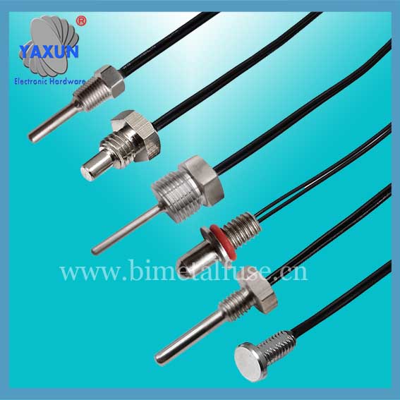
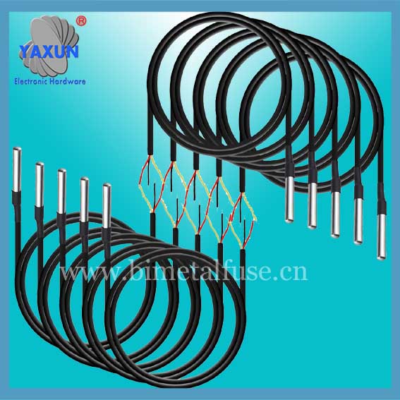
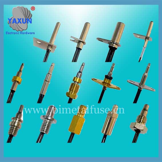
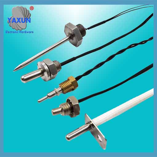
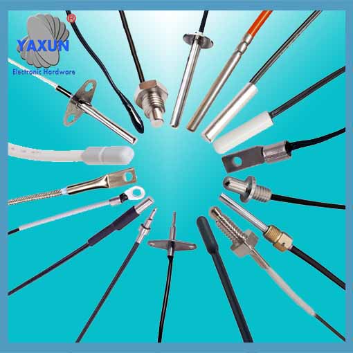
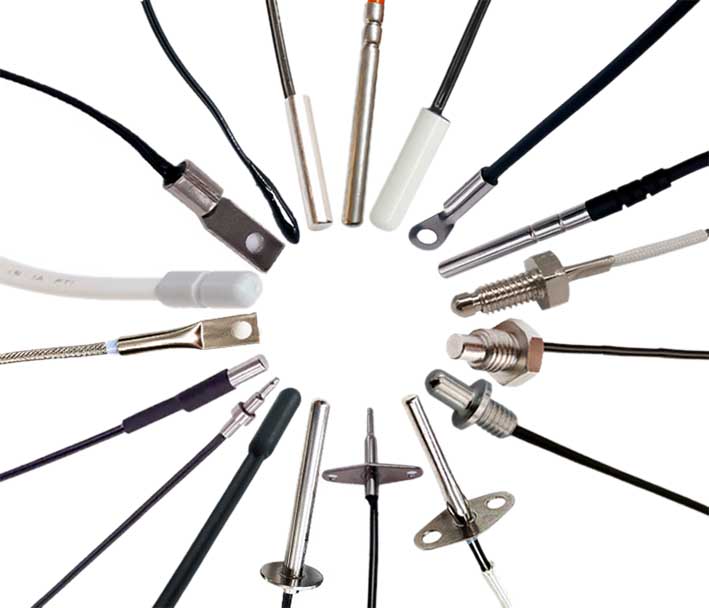
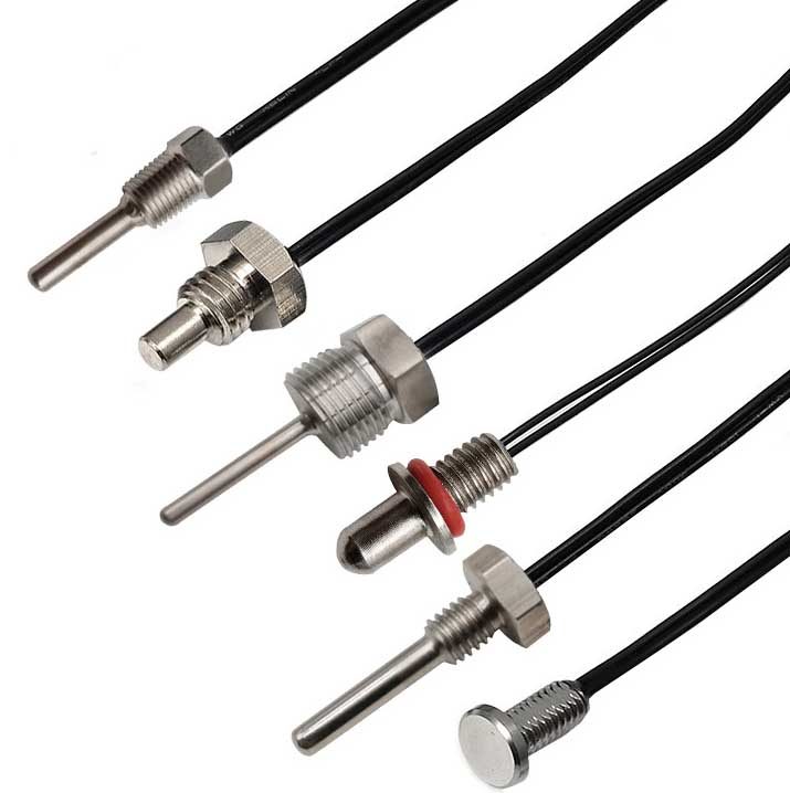
The waterproof DS18B20 digital temperature sensor probe and cable are easy to connect and can be used in a variety of situations after being packaged. Such as stainless steel straight pipe type, threaded type, magnet adsorption type, various models, including LTM8877, LTM8874 and so on.
DS18B20 is a commonly used digital temperature sensor. It outputs a digital signal and has the characteristics of small size, low hardware overhead, strong anti-interference ability and high accuracy. Its appearance mainly changes depending on the application. The encapsulated DS18B20 can be used for cable temperature measurement, blast furnace water circulation temperature measurement, boiler temperature measurement, machine room temperature measurement, agricultural greenhouse temperature measurement, clean room temperature measurement, ammunition depot temperature measurement and other non-limit temperature occasions. Wear-resistant and impact-resistant, small in size, easy to use, with various packaging forms, it is suitable for digital temperature measurement and control of various small space equipment.
 |
 |
| ds18b20 temperature sensor probe | Customized ds18b20 sensor cable |
Main features of DS18B20 sensor probe
1. Main features of DS18B20
1.1. The adaptable voltage range is wider, voltage range: 3.0~5.5V, and can be powered by the data line in parasitic power mode
1.2. Unique single-wire interface method. When DS18B20 is connected to the microprocessor, it only needs one port line to achieve two-way communication between the microprocessor and DS18B20.
1.3. DS18B20 supports multi-point networking function. Multiple DS18B20 can be connected in parallel on the only three lines to achieve multi-point temperature measurement.
1.4. DS18B20 does not require any external components during use. All sensing components and conversion circuits are integrated into an integrated circuit shaped like a triode.
1.5. Temperature range -55℃~+125℃, accuracy is ±0.5℃ at -10~+85℃
1.6. The programmable resolution is 9~12 bits, and the corresponding resolvable temperatures are 0.5℃, 0.25℃, 0.125℃ and 0.0625℃ respectively, which can achieve high-precision temperature measurement.
1.7. At 9-bit resolution, the temperature can be converted into numbers in up to 93.75ms. At 12-bit resolution, the temperature value can be converted into numbers in up to 750ms, which is faster.
1.8. The measurement results directly output digital temperature signals and are serially transmitted to the CPU via the "one-line bus". At the same time, the CRC check code can be transmitted, which has strong anti-interference and error correction capabilities.
1.9. Negative voltage characteristics: When the polarity of the power supply is reversed, the chip will not be burned due to heat, but it will not work properly.
2. Appearance and internal structure of DS18B20 sensor
The internal structure of the DS18B20 sensor mainly consists of four parts: 64-bit photolithography ROM, temperature sensor, non-volatile temperature alarm triggers TH and TL, and configuration register.
The appearance and pin arrangement of DS18B20 are as follows:
DS18B20 pin definition:
(1) DQ is the digital signal input/output terminal;
(2) GND is the power ground;
(3) VDD is the input terminal of the external power supply (grounded in the parasitic power wiring mode).
3. Working principle of DS18B20
The reading and writing timing and temperature measurement principle of DS18B20 are the same as those of DS1820, except that the number of digits of the temperature value obtained is different due to different resolutions, and the delay time during temperature conversion is reduced from 2s to 750ms. The oscillation rate of high temperature coefficient crystal oscillator changes significantly with temperature changes, and the generated signal is used as the pulse input of counter 2. Counter 1 and the temperature register are preset at a base value corresponding to -55°C. Counter 1 counts down the pulse signal generated by the low temperature coefficient crystal oscillator. When the preset value of counter 1 decreases to 0, the value of the temperature register will be increased by 1, the preset value of counter 1 will be reloaded, and counter 1 will restart counting the pulse signals generated by the low temperature coefficient crystal oscillator. This cycle continues until counter 2 counts to 0, then stops accumulating the temperature register value. At this time, the value in the temperature register is the measured temperature. The slope accumulator in Figure 3 is used to compensate and correct the nonlinearity in the temperature measurement process, and its output is used to correct the preset value of counter 1.
DS18B20 has 4 main data components:
(1) The 64-bit serial number in the photoetched ROM is photoetched before leaving the factory. It can be regarded as the address serial code of the DS18B20. The arrangement of the 64-bit photolithography ROM is: the first 8 bits (28H) are the product type number, and the next 48 bits are the serial number of the DS18B20 itself. The last 8 bits are the cyclic redundancy check code of the previous 56 bits (CRC=X8+X5+X4+1). The function of photolithography ROM is to make each DS18B20 different, so that multiple DS18B20s can be connected to one bus.
(2) The temperature sensor in DS18B20 can complete the measurement of temperature. Take 12-bit conversion as an example: it is provided in the form of 16-bit sign-extended two's complement reading, expressed in the form of 0.0625°C/LSB, where S is the sign bit.
This is the 12-bit data obtained after 12-bit conversion, which is stored in two 8-bit RAMs of 18B20. The first 5 bits in binary are the sign bits. If the measured temperature is greater than 0, these 5 bits are 0. Just multiply the measured value by 0.0625 to get the actual temperature. If the temperature is less than 0, these 5 bits are 1, and the measured value needs to be inverted, plus 1, and then multiplied by 0.0625 to get the actual temperature. For example, the digital output of +125℃ is 07D0H, the digital output of +25.0625℃ is 0191H, the digital output of -25.0625℃ is FE6FH, and the digital output of -55℃ is FC90H.
(3) DS18B20 temperature sensor memory DS18B20. The internal memory of the temperature sensor includes a high-speed scratchpad RAM and a non-volatile electrically erasable EEPRAM, which stores the high-temperature and low-temperature flip-flops TH, TL and structural registers.
(4) Configuration register The meaning of each bit of this byte is as follows:
Table 3: Configuration register structure
The lower five bits are always "1", and TM is the test mode bit, which is used to set whether the DS18B20 is in working mode or test mode. This bit is set to 0 when DS18B20 leaves the factory, and users should not change it. R1 and R0 are used to set the resolution, as shown in the following table: (DS18B20 is set to 12 bits when shipped from the factory)
Table 4: Temperature resolution setting table
4. High-speed temporary storage memory The high-speed temporary storage memory consists of 9 bytes, and its allocation is shown in Table 5. When the temperature conversion command is issued, the converted temperature value is stored in the 0th and 1st bytes of the cache memory in two-byte complement form. The microcontroller can read this data through the single-wire interface. When reading, the low bit is in front and the high bit is in the back. The data format is shown in Table 1. Corresponding temperature calculation: When the sign bit S=0, directly convert the binary bit to decimal; when S=1, first convert the complement to the original code, and then calculate the decimal value. Table 2 shows some of the corresponding temperature values. The ninth byte is the redundancy check byte.
Table 5: DS18B20 temporary register distribution
According to the communication protocol of DS18B20, the host (single chip microcomputer) must go through three steps to control DS18B20 to complete temperature conversion: DS18B20 must be reset before each read and write. After the reset is successful, a ROM command is sent, and finally a RAM command is sent, so that the predetermined operation can be performed on the DS18B20. Reset requires the main CPU to pull the data line down for 500 microseconds and then release it. When DS18B20 receives the signal, it waits for about 16 to 60 microseconds, and then sends out a low pulse of 60 to 240 microseconds. The main CPU receives this signal to indicate successful reset.
Table 6: ROM instruction list