Digital Temperature Sensor Ds18b20 Supplier
- PRODUCT DETAIL
There are many types of temperature sensors, and the DS18B20 temperature sensor produced by DALLAS is the best when used in high-precision and high-reliability applications. Ultra-small size, ultra-low hardware overhead, strong anti-interference ability, high precision, and strong additional functions make DS18B20 more popular. The advantages of DS18B20 are our best choice for learning microcontroller technology and developing temperature-related small products. Understanding the working principles and applications can broaden your ideas for microcontroller development.
2. Features of DS18B20
1. Communication uses 1-Wire interface
2. Each DS18B20 has a unique 64-bit serial code stored in the onboard ROM.
3. No external components required
4. It can be powered from the data line, and the power supply range is 3.0V ~ 5.5V.
5. The measurable temperature range is -55℃ ~ +125℃
6. The accuracy is ±0.5℃ in the range of -10~+85℃
7. The thermometer resolution can be set to 9~12 bits. At 12 bits, the resolution corresponds to 0.0625℃.
3. Typical connection methods of DS18B20 in practical applications
1. Typical connection method when working under parasitic power supply
4. Single bus timing
DS18B20 uses 1-wire Bus to transmit all data on one line, so the single-wire protocol has very strict timing requirements to ensure data integrity.
Single bus signal types: reset pulse, presence pulse, write 0, write 1, read 0, read 1. All these signals except the presence pulse sent by DS18B20, other signals are sent by the bus controller.
Data transfer always starts with the least significant bit.
Initialization timing
The initialization sequence includes resetting DS18B20 and receiving the presence signal returned by DS18B20.
The host needs to initialize it before any communication with DS18B20. During initialization, the bus controller pulls the bus low and holds it for more than 480us. The device hanging on the bus will be reset, then release the bus, wait until 15-60us, at which time 18B20 will return a low-level presence signal between 60-240us.
Reset pulse and presence pulse timing diagram:
DS18B20 application circuit DS18B20 temperature measurement system has the advantages of simple temperature measurement system, high temperature measurement accuracy, convenient connection, and takes up less interface lines. The following is the temperature measurement circuit diagram of DS18B20 in several different application modes:
5.1. The circuit diagram of DS18B20 parasitic power supply mode is shown in Figure 4. In the parasitic power supply mode, the DS18B20 draws energy from the single-wire signal line: the energy is stored in the internal capacitor while the signal line DQ is at a high level. When the signal line is at a low level, it consumes the power on the capacitor to work, and then charges the parasitic power supply (capacitor) until the high level arrives.
The unique parasitic power supply method has three benefits:
1) When performing remote temperature measurement, no local power supply is required
2) ROM can be read without regular power supply
3) The circuit is simpler, using only one I/O port to measure temperature.
For the DS18B20 to perform accurate temperature conversions, the I/O lines must ensure sufficient energy is provided during the temperature conversion. Since the operating current of each DS18B20 reaches 1mA during temperature conversion, when several temperature sensors are hung on the same I/O line for multi-point temperature measurement, the 4.7K pull-up resistor alone cannot provide enough energy. It will cause the temperature to be unable to be converted or the temperature error to be extremely large.
Therefore, the circuit in Figure 4 is only suitable for use in temperature measurement with a single temperature sensor and is not suitable for use in battery-powered systems. And the working power supply VCC must be guaranteed to be 5V. When the power supply voltage drops, the energy that the parasitic power supply can draw also decreases, which will increase the temperature error.
5.2. DS18B20 parasitic power supply strong pull-up power supply mode circuit diagram The improved parasitic power supply mode is shown in Figure 5. In order for the DS18B20 to obtain sufficient current supply during the dynamic conversion cycle, when performing temperature conversion or copying to the E2 memory operation, using a MOSFET to directly pull the I/O line to VCC can provide sufficient current. The I/O line must be transitioned to a strong pull-up state within a maximum of 10 μS after issuing any command involving a copy to E2 memory or the initiation of a temperature conversion. The strong pull-up mode can solve the problem of current supply failure, so it is also suitable for multi-point temperature measurement applications. The disadvantage is that it takes up one more I/O port line for strong pull-up switching.
Note: In the parasitic power supply mode of Figure 4 and Figure 5, the VDD pin of DS18B20 must be connected to ground.
5.3. External power supply mode of DS18B20
In the external power supply mode, the DS18B20 working power supply is connected to the VDD pin. At this time, the I/O line does not need a strong pull-up, and there is no problem of insufficient power supply current, which can ensure the conversion accuracy. At the same time, any number of DS18B20 sensors can theoretically be connected to the bus to form a multi-point temperature measurement system. Note: In external power supply mode, the GND pin of DS18B20 cannot be left floating, otherwise the temperature cannot be converted and the read temperature is always 85°C.
The external power supply method is the best working method of DS18B20. The work is stable and reliable, the anti-interference ability is strong, and the circuit is relatively simple, so a stable and reliable multi-point temperature monitoring system can be developed. The webmaster recommends that you use an external power supply during development. After all, there is only one more VCC lead than the parasitic power supply. In the external power supply mode, the advantages of the wide power supply voltage range of the DS18B20 can be fully utilized. Even if the power supply voltage VCC drops to 3V, the temperature measurement accuracy can still be guaranteed.
6. Precautions when using DS1820
Although DS1820 has the advantages of simple temperature measurement system, high temperature measurement accuracy, convenient connection, and takes up less interface lines, the following issues should also be paid attention to in practical applications:
6.1. Small hardware overhead requires relatively complex software to compensate. Since serial data transmission is used between DS1820 and the microprocessor, when reading and writing programming to DS1820, the reading and writing timing must be strictly guaranteed, otherwise the temperature measurement results will not be read. When using high-level languages such as PL/M and C for system programming, it is best to use assembly language to implement the DS1820 operation part.
6.2. The relevant information on DS1820 does not mention the number of DS1820s connected to a single bus, which may easily lead people to mistakenly believe that any number of DS1820s can be connected. In practical applications this is not the case. When there are more than 8 DS1820s on a single bus, the bus driver problem of the microprocessor needs to be solved. This point should be paid attention to when designing a multi-point temperature measurement system.
6.3. The bus cable connected to DS1820 has a length limit. During the test, when the transmission length exceeds 50m using ordinary signal cables, errors will occur in the temperature measurement data read. When the bus cable is changed to a twisted pair shielded cable, the normal communication distance can reach 150m. When a twisted-pair shielded cable with more twists per meter is used, the normal communication distance is further lengthened. This situation is mainly caused by the distortion of the signal waveform caused by the bus distributed capacitance. Therefore, when designing a long-distance temperature measurement system using DS1820, the bus distributed capacitance and impedance matching issues must be fully considered.
6.4. In the design of the DS1820 temperature measurement program, after sending a temperature conversion command to the DS1820, the program always waits for the return signal from the DS1820. Once a DS1820 has poor contact or is disconnected, when the program reads the DS1820, there will be no return signal and the program will enter an infinite loop. This point should also be given certain attention when performing DS1820 hardware connection and software design. It is recommended that the temperature measurement cable be shielded 4-core twisted pair. One pair of wires is connected to the ground wire and signal wire, the other group is connected to VCC and ground wire, and the shielding layer is grounded at a single point at the source end.
 |
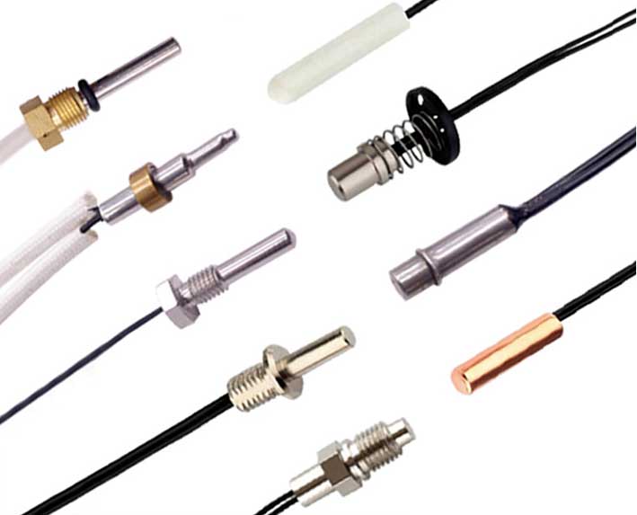 |
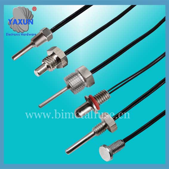
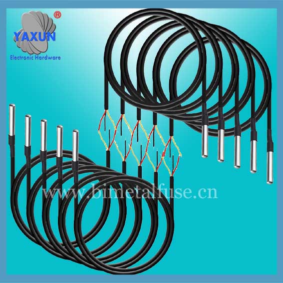
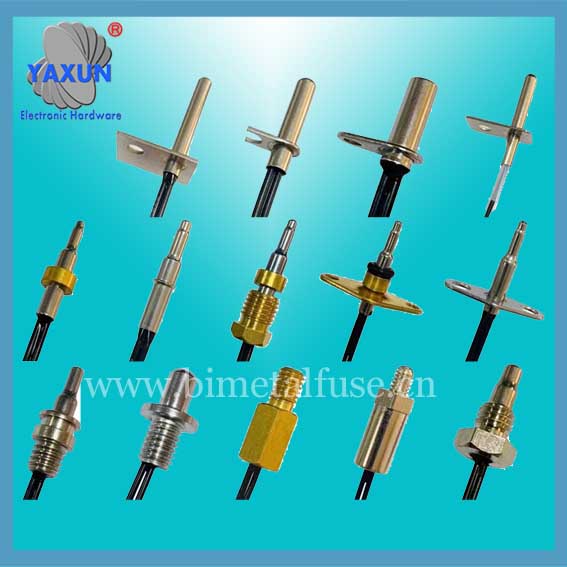
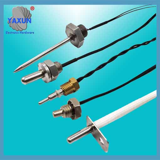
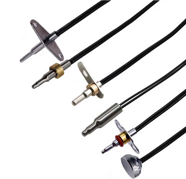
| waterproof arduino ds18b20 sensor probe | ds18b20 one wire temperature sensor circuit |
2. Features of DS18B20
1. Communication uses 1-Wire interface
2. Each DS18B20 has a unique 64-bit serial code stored in the onboard ROM.
3. No external components required
4. It can be powered from the data line, and the power supply range is 3.0V ~ 5.5V.
5. The measurable temperature range is -55℃ ~ +125℃
6. The accuracy is ±0.5℃ in the range of -10~+85℃
7. The thermometer resolution can be set to 9~12 bits. At 12 bits, the resolution corresponds to 0.0625℃.
3. Typical connection methods of DS18B20 in practical applications
1. Typical connection method when working under parasitic power supply
4. Single bus timing
DS18B20 uses 1-wire Bus to transmit all data on one line, so the single-wire protocol has very strict timing requirements to ensure data integrity.
Single bus signal types: reset pulse, presence pulse, write 0, write 1, read 0, read 1. All these signals except the presence pulse sent by DS18B20, other signals are sent by the bus controller.
Data transfer always starts with the least significant bit.
Initialization timing
The initialization sequence includes resetting DS18B20 and receiving the presence signal returned by DS18B20.
The host needs to initialize it before any communication with DS18B20. During initialization, the bus controller pulls the bus low and holds it for more than 480us. The device hanging on the bus will be reset, then release the bus, wait until 15-60us, at which time 18B20 will return a low-level presence signal between 60-240us.
Reset pulse and presence pulse timing diagram:
DS18B20 application circuit DS18B20 temperature measurement system has the advantages of simple temperature measurement system, high temperature measurement accuracy, convenient connection, and takes up less interface lines. The following is the temperature measurement circuit diagram of DS18B20 in several different application modes:
5.1. The circuit diagram of DS18B20 parasitic power supply mode is shown in Figure 4. In the parasitic power supply mode, the DS18B20 draws energy from the single-wire signal line: the energy is stored in the internal capacitor while the signal line DQ is at a high level. When the signal line is at a low level, it consumes the power on the capacitor to work, and then charges the parasitic power supply (capacitor) until the high level arrives.
The unique parasitic power supply method has three benefits:
1) When performing remote temperature measurement, no local power supply is required
2) ROM can be read without regular power supply
3) The circuit is simpler, using only one I/O port to measure temperature.
For the DS18B20 to perform accurate temperature conversions, the I/O lines must ensure sufficient energy is provided during the temperature conversion. Since the operating current of each DS18B20 reaches 1mA during temperature conversion, when several temperature sensors are hung on the same I/O line for multi-point temperature measurement, the 4.7K pull-up resistor alone cannot provide enough energy. It will cause the temperature to be unable to be converted or the temperature error to be extremely large.
Therefore, the circuit in Figure 4 is only suitable for use in temperature measurement with a single temperature sensor and is not suitable for use in battery-powered systems. And the working power supply VCC must be guaranteed to be 5V. When the power supply voltage drops, the energy that the parasitic power supply can draw also decreases, which will increase the temperature error.
5.2. DS18B20 parasitic power supply strong pull-up power supply mode circuit diagram The improved parasitic power supply mode is shown in Figure 5. In order for the DS18B20 to obtain sufficient current supply during the dynamic conversion cycle, when performing temperature conversion or copying to the E2 memory operation, using a MOSFET to directly pull the I/O line to VCC can provide sufficient current. The I/O line must be transitioned to a strong pull-up state within a maximum of 10 μS after issuing any command involving a copy to E2 memory or the initiation of a temperature conversion. The strong pull-up mode can solve the problem of current supply failure, so it is also suitable for multi-point temperature measurement applications. The disadvantage is that it takes up one more I/O port line for strong pull-up switching.
Note: In the parasitic power supply mode of Figure 4 and Figure 5, the VDD pin of DS18B20 must be connected to ground.
5.3. External power supply mode of DS18B20
In the external power supply mode, the DS18B20 working power supply is connected to the VDD pin. At this time, the I/O line does not need a strong pull-up, and there is no problem of insufficient power supply current, which can ensure the conversion accuracy. At the same time, any number of DS18B20 sensors can theoretically be connected to the bus to form a multi-point temperature measurement system. Note: In external power supply mode, the GND pin of DS18B20 cannot be left floating, otherwise the temperature cannot be converted and the read temperature is always 85°C.
The external power supply method is the best working method of DS18B20. The work is stable and reliable, the anti-interference ability is strong, and the circuit is relatively simple, so a stable and reliable multi-point temperature monitoring system can be developed. The webmaster recommends that you use an external power supply during development. After all, there is only one more VCC lead than the parasitic power supply. In the external power supply mode, the advantages of the wide power supply voltage range of the DS18B20 can be fully utilized. Even if the power supply voltage VCC drops to 3V, the temperature measurement accuracy can still be guaranteed.
6. Precautions when using DS1820
Although DS1820 has the advantages of simple temperature measurement system, high temperature measurement accuracy, convenient connection, and takes up less interface lines, the following issues should also be paid attention to in practical applications:
6.1. Small hardware overhead requires relatively complex software to compensate. Since serial data transmission is used between DS1820 and the microprocessor, when reading and writing programming to DS1820, the reading and writing timing must be strictly guaranteed, otherwise the temperature measurement results will not be read. When using high-level languages such as PL/M and C for system programming, it is best to use assembly language to implement the DS1820 operation part.
6.2. The relevant information on DS1820 does not mention the number of DS1820s connected to a single bus, which may easily lead people to mistakenly believe that any number of DS1820s can be connected. In practical applications this is not the case. When there are more than 8 DS1820s on a single bus, the bus driver problem of the microprocessor needs to be solved. This point should be paid attention to when designing a multi-point temperature measurement system.
6.3. The bus cable connected to DS1820 has a length limit. During the test, when the transmission length exceeds 50m using ordinary signal cables, errors will occur in the temperature measurement data read. When the bus cable is changed to a twisted pair shielded cable, the normal communication distance can reach 150m. When a twisted-pair shielded cable with more twists per meter is used, the normal communication distance is further lengthened. This situation is mainly caused by the distortion of the signal waveform caused by the bus distributed capacitance. Therefore, when designing a long-distance temperature measurement system using DS1820, the bus distributed capacitance and impedance matching issues must be fully considered.
6.4. In the design of the DS1820 temperature measurement program, after sending a temperature conversion command to the DS1820, the program always waits for the return signal from the DS1820. Once a DS1820 has poor contact or is disconnected, when the program reads the DS1820, there will be no return signal and the program will enter an infinite loop. This point should also be given certain attention when performing DS1820 hardware connection and software design. It is recommended that the temperature measurement cable be shielded 4-core twisted pair. One pair of wires is connected to the ground wire and signal wire, the other group is connected to VCC and ground wire, and the shielding layer is grounded at a single point at the source end.
PREV:Waterproof Ds18b20 Sensor Probe and Cable
NEXT:NONE
NEXT:NONE