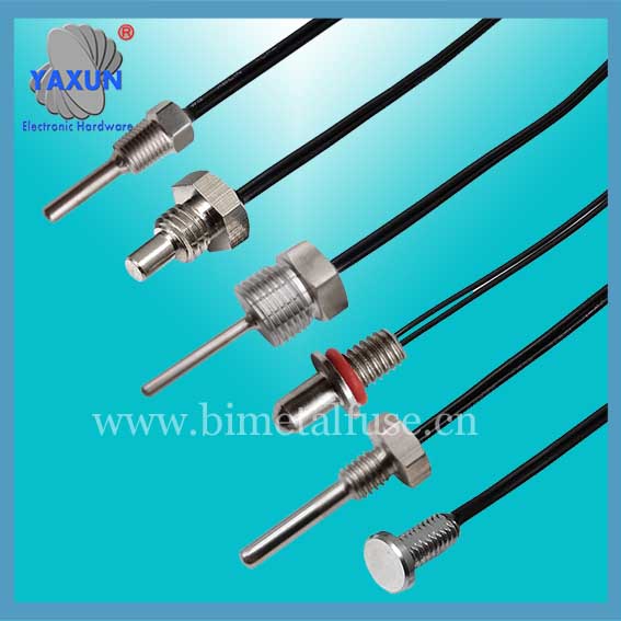
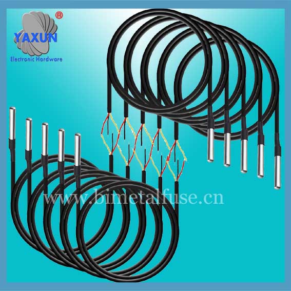
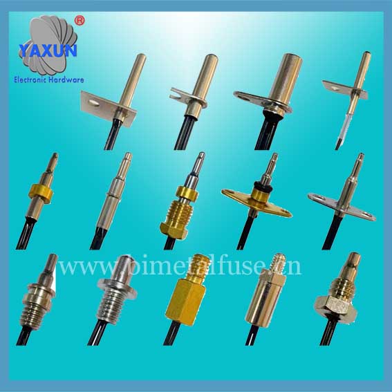
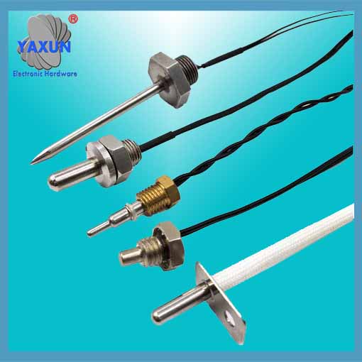
Ds18b20 Temperature Probe Cable
- PRODUCT DETAIL
DS18B20, DS1822 "One-line bus" digital temperature sensor Same as DS1820. DS18B20 also supports "one-line bus" interface, and the measurement temperature range is -55°C~+125°C, and the accuracy is ±0.5°C in the range of -10~+85°C. The accuracy of the DS1822 is ±2°C. The on-site temperature is directly transmitted digitally via the "one-line bus", which greatly improves the system's anti-interference capability. Suitable for on-site temperature measurement in harsh environments, such as environmental control, equipment or process control, temperature measurement consumer electronics, etc. The new product supports a voltage range of 3V~5.5V, making system design more flexible and convenient. And the new generation of products is cheaper and smaller. Features of DS18B20 and DS1822 DS18B20 can be programmed with a resolution of 9~12 bits and an accuracy of ±0.5°C. Optional smaller package, wider voltage range. The resolution setting and the user-set alarm temperature are stored in EEPROM and are still saved after power off. The performance of DS18B20 is the best among the new generation products! The price-performance ratio is also excellent! The DS1822 is software compatible with the DS18B20 and is a simplified version of the DS18B20. The EEPROM that stores user-defined alarm temperature and resolution parameters is omitted, and the accuracy is reduced to ±2°C. It is suitable for applications with low performance requirements and strict cost control. It is an economical product. Following the early products of the "One Line Bus", the DS1820 opens up a new concept in temperature sensor technology. DS18B20 and DS1822 provide more choices in voltage, characteristics and packaging, allowing us to build an economical temperature measurement system that suits us.
Internal structure of ds18b20 temperature probe
The internal structure of DS18B20 mainly consists of four parts:
64-bit photolithography ROM, temperature sensor, non-volatile temperature alarm trigger TH and TL, configuration register.
The pin arrangement of DS18B20 is as follows
DQ is the digital signal input/output terminal; GND is the power ground; VDD is the external power supply input terminal (grounded in the parasitic power wiring mode).
The 64-bit serial number in the photoetched ROM is photoetched before leaving the factory. It can be regarded as the address serial code of the DS18B20. The arrangement of the 64-bit photolithography ROM is: the first 8 bits (28H) are the product type number, the next 48 bits are the serial number of the DS18B20 itself, and the last 8 bits are the previous 56-bit cyclic redundancy check code (CRC=X8 +X5+X4+1). The purpose of the photolithography ROM is to make each DS18B20 different, so that multiple DS18B20s can be connected to one bus.
The temperature sensor in DS18B20 can complete the measurement of temperature. Take 12-bit conversion as an example: it is provided in the form of a 16-bit sign-extended two's complement reading, expressed in the form of 0.0625°C/LSB, where S is the sign bit.
This is the 12-bit data obtained after 12-bit conversion, which is stored in two 8-bit RAMs of 18B20. The first 5 bits in binary are sign bits if the measured temperature is greater than 0. These 5 bits are 0. Just multiply the measured value by 0.0625 to get the actual temperature. If the temperature is less than 0, these 5 bits are 1, and the measured value needs to be inverted, plus 1, and then multiplied by 0.0625 to get the actual temperature.
For example, the digital output of +125℃ is 07D0H, the digital output of +25.0625℃ is 0191H, the digital output of -25.0625℃ is FE6FH, and the digital output of -55℃ is FC90H.
DS18B20 temperature sensor memory
The internal memory of the DS18B20 temperature sensor includes a high-speed scratchpad RAM and a non-volatile electrically erasable E2RAM, which stores high-temperature and low-temperature triggers TH, TL and structural registers.
The temporary storage memory contains 8 consecutive bytes, the first two bytes are the measured temperature information. The content of the first byte is the lower eight bits of the temperature. The second byte is the high eight bits of the temperature. The third and fourth bytes are volatile copies of TH and TL, and the fifth byte is a volatile copy of the architectural register. The contents of these three bytes are refreshed at each power-on reset. The sixth, seventh, and eighth bytes are used for internal calculations. The ninth byte is the redundancy check byte.
The meaning of each bit of this byte is as follows:
TM R1 R0 1 1 1 1 1
The lower five bits are always 1. TM is the test mode bit, which is used to set whether the DS18B20 is in working mode or test mode. This bit is set to 0 when DS18B20 leaves the factory, and users should not change it. R1 and R0 are used to set the resolution, as shown in the following table: (DS18B20 is set to 12 bits when shipped from the factory)
Resolution setting table:
R1 R0 Resolution Temperature Maximum Conversion Time
0 0 9 bits 93.75ms
0 1 10 bits 187.5ms
1 0 11 bits 375ms
1 1 12 bits 750ms
According to the communication protocol of DS18B20, the host must go through three steps to control DS18B20 to complete the temperature conversion: DS18B20 must be reset before each read and write, and a ROM command is sent after the reset is successful. Finally, the RAM command is sent so that the DS18B20 can be operated as scheduled. Reset requires the main CPU to pull the data line down for 500 microseconds and then release it. After receiving the signal, DS18B20 waits for about 16 to 60 microseconds, and then sends out a low pulse of 60 to 240 microseconds. The main CPU receives this signal to indicate successful reset.