Read the Temperature Value of PT100 Sensor Through MAX31865
Design a solution for reading the temperature value of PT100/PT1000 temperature sensor:
MAX31865 Description:
The MAX31865 is a simple and easy-to-use thermistor to digital output converter produced by Maxim Corporation. Optimized for use with platinum resistance temperature detectors (RTDs).
Features:
· RTD sensitivity can be set through external resistors;
· With ±45V input protection, fault detection of cable open circuit and short circuit conditions, RTD configurable;
· Built-in high-precision delta-sigma ADC converter with nominal temperature resolution of 0.03125°C (non-linear variation with RTD);
· Compatible with 2-wire, 3-wire, and 4-wire sensors;
· The maximum conversion time is 21ms;
 Package and pin description:
Hardware circuit:
Official reference circuit:
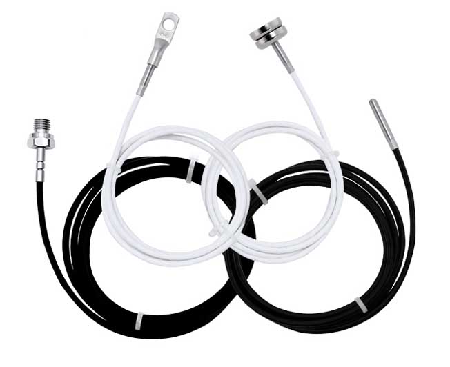
1. 2-wire pt100:
3-wire pt100:
4-wire pt100:
Some people here may not understand the two-wire, three-wire, and four-wire systems of PT100. Here is a brief introduction:
The two-wire system is a method in which a wire is connected to both ends of the thermal resistor. However, this method of wiring is relatively simple, and there is resistance on the leads, which will bring certain errors to the measurement. Therefore, it is used when the measurement accuracy is relatively low.
The three-wire system is to connect one lead to one end of the thermal resistor and two leads to the other end. This method usually can better eliminate the influence of line resistance. It is usually used in conjunction with an electric bridge and is also a commonly used method in industry.
The four-wire system connects two wires to each end of the thermal resistor. When two of the leads are used, a constant current source is added to the thermal resistor current, and then the current signal is converted into a voltage signal through the thermal resistor, and the voltage is drawn out through the other two wires for measurement. This wiring method can completely eliminate the influence of wire resistance and is often used in situations where temperature accuracy is high.
Programming
Before writing the program, we must read the chip manual, which can be seen from the chip manual. The MAX31856 uses SPI communication to support mode 1 and mode 3. The frequency during communication should not exceed 5Mz. There are 16 register files inside the chip for the operation of the chip. Mainly when reading or writing to access the register, use address 0Xh for read operations and address 8Xh for write operations. The main registers are shown in the figure below:
When programming, you should pay attention to the configuration of the registers. Here we mainly pay attention to the following registers.
1.Configuration register
2. RTD resistance register (01-02H)
Two 8-bit registers, RTD MSB and RTD LSB, contain the RTD resistance data. The data format is as follows: The data format is the ratio of the RTD resistance to the reference resistance, containing 15 bits of valid data. D0 of the RTD LSB register is the fault bit, indicating whether any RTD fault is detected.
Temperature conversion:
For PT thermistors, the most common resistance values are: the nominal values are 100 ohms and 1K ohms at 0 degrees Celsius, and the two common values for the average slope between 0-100 degrees Celsius are: 0.00385 and 0.00392. The relationship curves between resistance and temperature corresponding to IEC751 and SMA standards are close to linear, but due to a certain bend, they can be expressed by the Kellendar-Van Dusen equation:
The main program for temperature conversion is as follows:
float MAX31865_GetTemp(void)
{
unsigned int data;
float Rt;
float Rt0 = 100; //The resistance value corresponding to PT100 0 degrees is c=0 when 0-850;
float Z1,Z2,Z3,Z4,temp;
float a = 3.9083e-3;
float b = -5.775e-7;
float rpoly; //
MAX31865_Write(0x80, 0xD3);
data=MAX31865_Read(0x01)<<8;//Read the resistance value from the register RTD resistance register
data|=MAX31865_Read(0x02);
data>>=1; //Remove the Fault bit
Rt=(float)data/32768.0*RREF; //Resistance conversion
/*Solve quadratic equations*/
Z1 = -a;
Z2 = a*a-4*b;
Z3 = 4*b/Rt0;
Z4 = 2*b;
temp = Z2+Z3*Rt;
temp = (sqrt(temp)+Z1)/Z4;
if(temp>=0) return temp;
rpoly = Rt;
temp = -242.02;
temp += 2.2228 * rpoly;
rpoly *= Rt; // square
temp += 2.5859e-3 * rpoly;
rpoly *= Rt; // ^3
temp -= 4.8260e-6 * rpoly;
rpoly *= Rt; // ^4
temp -= 2.8183e-8 * rpoly;
rpoly *= Rt; // ^5
temp += 1.5243e-10 * rpoly;
return temp;
}
MAX31865 Description:
The MAX31865 is a simple and easy-to-use thermistor to digital output converter produced by Maxim Corporation. Optimized for use with platinum resistance temperature detectors (RTDs).
Features:
· RTD sensitivity can be set through external resistors;
· With ±45V input protection, fault detection of cable open circuit and short circuit conditions, RTD configurable;
· Built-in high-precision delta-sigma ADC converter with nominal temperature resolution of 0.03125°C (non-linear variation with RTD);
· Compatible with 2-wire, 3-wire, and 4-wire sensors;
· The maximum conversion time is 21ms;
Hardware circuit:
Official reference circuit:
1. 2-wire pt100:
3-wire pt100:
4-wire pt100:
Some people here may not understand the two-wire, three-wire, and four-wire systems of PT100. Here is a brief introduction:
The two-wire system is a method in which a wire is connected to both ends of the thermal resistor. However, this method of wiring is relatively simple, and there is resistance on the leads, which will bring certain errors to the measurement. Therefore, it is used when the measurement accuracy is relatively low.
The three-wire system is to connect one lead to one end of the thermal resistor and two leads to the other end. This method usually can better eliminate the influence of line resistance. It is usually used in conjunction with an electric bridge and is also a commonly used method in industry.
The four-wire system connects two wires to each end of the thermal resistor. When two of the leads are used, a constant current source is added to the thermal resistor current, and then the current signal is converted into a voltage signal through the thermal resistor, and the voltage is drawn out through the other two wires for measurement. This wiring method can completely eliminate the influence of wire resistance and is often used in situations where temperature accuracy is high.
Programming
Before writing the program, we must read the chip manual, which can be seen from the chip manual. The MAX31856 uses SPI communication to support mode 1 and mode 3. The frequency during communication should not exceed 5Mz. There are 16 register files inside the chip for the operation of the chip. Mainly when reading or writing to access the register, use address 0Xh for read operations and address 8Xh for write operations. The main registers are shown in the figure below:
When programming, you should pay attention to the configuration of the registers. Here we mainly pay attention to the following registers.
1.Configuration register
2. RTD resistance register (01-02H)
Two 8-bit registers, RTD MSB and RTD LSB, contain the RTD resistance data. The data format is as follows: The data format is the ratio of the RTD resistance to the reference resistance, containing 15 bits of valid data. D0 of the RTD LSB register is the fault bit, indicating whether any RTD fault is detected.
Temperature conversion:
For PT thermistors, the most common resistance values are: the nominal values are 100 ohms and 1K ohms at 0 degrees Celsius, and the two common values for the average slope between 0-100 degrees Celsius are: 0.00385 and 0.00392. The relationship curves between resistance and temperature corresponding to IEC751 and SMA standards are close to linear, but due to a certain bend, they can be expressed by the Kellendar-Van Dusen equation:
The main program for temperature conversion is as follows:
float MAX31865_GetTemp(void)
{
unsigned int data;
float Rt;
float Rt0 = 100; //The resistance value corresponding to PT100 0 degrees is c=0 when 0-850;
float Z1,Z2,Z3,Z4,temp;
float a = 3.9083e-3;
float b = -5.775e-7;
float rpoly; //
MAX31865_Write(0x80, 0xD3);
data=MAX31865_Read(0x01)<<8;//Read the resistance value from the register RTD resistance register
data|=MAX31865_Read(0x02);
data>>=1; //Remove the Fault bit
Rt=(float)data/32768.0*RREF; //Resistance conversion
/*Solve quadratic equations*/
Z1 = -a;
Z2 = a*a-4*b;
Z3 = 4*b/Rt0;
Z4 = 2*b;
temp = Z2+Z3*Rt;
temp = (sqrt(temp)+Z1)/Z4;
if(temp>=0) return temp;
rpoly = Rt;
temp = -242.02;
temp += 2.2228 * rpoly;
rpoly *= Rt; // square
temp += 2.5859e-3 * rpoly;
rpoly *= Rt; // ^3
temp -= 4.8260e-6 * rpoly;
rpoly *= Rt; // ^4
temp -= 2.8183e-8 * rpoly;
rpoly *= Rt; // ^5
temp += 1.5243e-10 * rpoly;
return temp;
}


