RTD Three-Wire PT100 Sensor Current
Many medical, process control and industrial automation applications require precise temperature measurement to function. Resistive temperature detectors (RTD sensors) are often used as the sensing element in these precise temperature measurements. Because they have a wide temperature measurement range, good linearity, and excellent long-term stability and repeatability. RTDs are sensing elements made of metal that have predictable resistance over the operating temperature range. The resistance of an RTD sensor can be calculated by injecting current through the RTD and measuring the voltage. The RTD temperature can then be calculated based on the relationship between the RTD resistance and temperature.
 This article discusses the principles and advantages of the RTD three-wire PT100 measurement system.
Pt100 RTD Overview
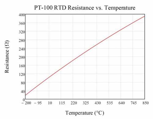
The Pt100 RTD is a platinum RTD sensor that provides excellent performance over a wide temperature range. Platinum is a precious metal that has the highest resistivity as a commonly used RTD material, enabling small-sized sensors. RTD sensors made of platinum are sometimes called platinum resistance thermometers or PRTs. The impedance of Pt100 RTD is 100Ω at 0℃, and every 1℃ temperature change will cause a resistance change of approximately 0.385Ω. When at the extremes of the available temperature range, the resistance is 18.51Ω (at -200°C) or 390.48Ω (at 850°C). Higher value resistive sensors such as Pt1000 or Pt5000 are available to increase sensitivity and resolution.
The Callendar Van-Dusen (CVD) equation explains the resistance characteristics of an RTD as a function of temperature (T, in degrees Celsius). When the temperature is positive, the CVD equation is a second-order polynomial, as shown in equation (1). When the temperature is negative, the CVD equation expands to the fourth-order polynomial shown in Equation (2).
CVD coefficients (A, B and C) are specified in the European IEC-60751 standard. Equation (3) shows these coefficient values. R0 is the resistance of the RTD at 0°C.
Figure 1 plots the change in resistance of a Pt100 RTD as the temperature increases from -200°C to 850°C.
Figure 1: Pt100 RTD resistor as temperature increases from -200°C to 850°C
Three-cable RTD
Three-wire RTD configurations are popular because they strike a balance between cost and accuracy. In the recommended three-wire configuration, an excitation current (I1) creates a voltage potential across the RTD element. At the same time, another excitation current (I2) is injected to offset the resistance of the RTD leads (RLEAD) from the final measurement, as shown in Figure 2 and Equation (4-7).
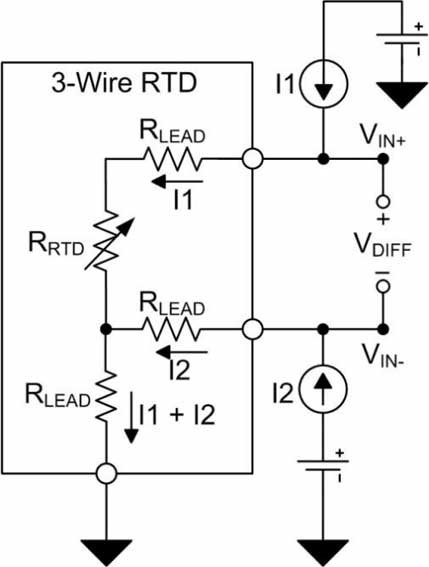 Figure 2: Three-wire RTD with lead resistance
RTD measurement circuit configuration
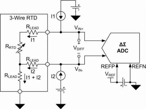
The differential RTD voltage VDIFF is typically converted by an analog-to-digital converter (ADC) and passed to the processor for interpretation. The ADC compares the input voltage to a reference voltage VREF to produce a digital output. Figure 3 shows a three-wire RTD measurement circuit using a discrete external reference voltage. Equation (8) defines the final conversion result based on the total number of digital codes, RTD resistance, excitation current magnitude, and reference voltage. This example assumes that the ADC has a full-scale range of ±VREF. As shown in the figure, errors due to the magnitude of the reference voltage and excitation current, noise, and temperature drift can directly lead to conversion errors.
Figure 3: Three-wire RTD circuit with external reference
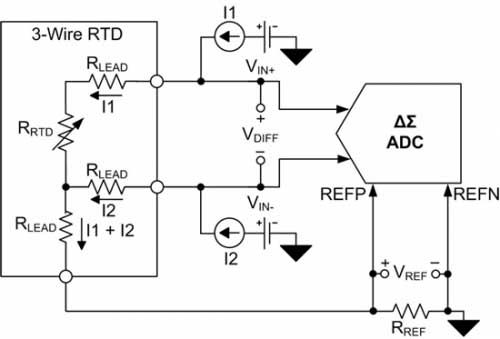
 Placing the RTD and ADC in a ratiometric configuration (Figure 4) results in a more accurate circuit configuration suitable for three-wire RTD systems. In a ratiometric configuration, the field current flowing through the RTD can be returned to ground through the low-side reference resistor RREF. The voltage potential VREF developed across RREF is provided to the positive and negative reference pins (REFP and REFN) of the ADC.
The voltage drop across the RTD and RREF resistors is produced by the same excitation current (Equation 9 and Equation 10). Therefore, changes in the excitation current are reflected in both the RTD differential voltage and the reference voltage. Since the ADC output code represents the relationship between the input voltage and the reference voltage, the final conversion result can be converted into the ratio of the RTD resistance and the RREF resistance and does not depend on the value of the reference voltage or the excitation current. Therefore, if the excitation current is perfectly matched and does not affect the final conversion result, then the errors caused by the size of the excitation current, temperature drift and noise can be eliminated. In addition, the proportional configuration also helps reduce the impact of external noise because this noise is also eliminated.
Figure 4: Proportional three-wire RTD circuit
 Excitation current source mismatch error
The two field currents must be equal to each other to achieve the ideal transfer function (Equation 11). Excitation current mismatch changes the ideal system transfer function because it reduces the effectiveness of lead resistance cancellation.
The most severe impact on the transfer function occurs when one field current is reduced or increased by an amount that reaches the limit specified by the mismatch specification. This is explained in equation (12) (where Δ represents the excitation current mismatch).
A mismatch in I2 can cause the ideal transfer function to change (Equation 13).
Equation (14) calculates the gain error due to excitation current mismatch by comparing the calculation of Equation (13) with the ideal transfer function of Equation (11).
If the field current loss is specified to be expressed in %FSR, then the gain error can be calculated as shown in Equation (15).
Gain errors caused by excitation current mismatch can be eliminated through standard gain calibration. However, field current mismatch often drifts with temperature, requiring complex calibration to correct.
Summarize
In this article we introduce three-wire RTDs, lead resistance cancellation, and the benefits of building a proportional three-wire RTD system. We point out that when the proportional RTD configuration removes the error from the initial accuracy of the excitation current, the mismatch between the two excitation currents still causes gain errors.
Pt100 RTD Overview
The Pt100 RTD is a platinum RTD sensor that provides excellent performance over a wide temperature range. Platinum is a precious metal that has the highest resistivity as a commonly used RTD material, enabling small-sized sensors. RTD sensors made of platinum are sometimes called platinum resistance thermometers or PRTs. The impedance of Pt100 RTD is 100Ω at 0℃, and every 1℃ temperature change will cause a resistance change of approximately 0.385Ω. When at the extremes of the available temperature range, the resistance is 18.51Ω (at -200°C) or 390.48Ω (at 850°C). Higher value resistive sensors such as Pt1000 or Pt5000 are available to increase sensitivity and resolution.
The Callendar Van-Dusen (CVD) equation explains the resistance characteristics of an RTD as a function of temperature (T, in degrees Celsius). When the temperature is positive, the CVD equation is a second-order polynomial, as shown in equation (1). When the temperature is negative, the CVD equation expands to the fourth-order polynomial shown in Equation (2).
CVD coefficients (A, B and C) are specified in the European IEC-60751 standard. Equation (3) shows these coefficient values. R0 is the resistance of the RTD at 0°C.
Figure 1 plots the change in resistance of a Pt100 RTD as the temperature increases from -200°C to 850°C.
Figure 1: Pt100 RTD resistor as temperature increases from -200°C to 850°C
Three-cable RTD
Three-wire RTD configurations are popular because they strike a balance between cost and accuracy. In the recommended three-wire configuration, an excitation current (I1) creates a voltage potential across the RTD element. At the same time, another excitation current (I2) is injected to offset the resistance of the RTD leads (RLEAD) from the final measurement, as shown in Figure 2 and Equation (4-7).
RTD measurement circuit configuration
The differential RTD voltage VDIFF is typically converted by an analog-to-digital converter (ADC) and passed to the processor for interpretation. The ADC compares the input voltage to a reference voltage VREF to produce a digital output. Figure 3 shows a three-wire RTD measurement circuit using a discrete external reference voltage. Equation (8) defines the final conversion result based on the total number of digital codes, RTD resistance, excitation current magnitude, and reference voltage. This example assumes that the ADC has a full-scale range of ±VREF. As shown in the figure, errors due to the magnitude of the reference voltage and excitation current, noise, and temperature drift can directly lead to conversion errors.
Figure 3: Three-wire RTD circuit with external reference
The voltage drop across the RTD and RREF resistors is produced by the same excitation current (Equation 9 and Equation 10). Therefore, changes in the excitation current are reflected in both the RTD differential voltage and the reference voltage. Since the ADC output code represents the relationship between the input voltage and the reference voltage, the final conversion result can be converted into the ratio of the RTD resistance and the RREF resistance and does not depend on the value of the reference voltage or the excitation current. Therefore, if the excitation current is perfectly matched and does not affect the final conversion result, then the errors caused by the size of the excitation current, temperature drift and noise can be eliminated. In addition, the proportional configuration also helps reduce the impact of external noise because this noise is also eliminated.
Figure 4: Proportional three-wire RTD circuit
The two field currents must be equal to each other to achieve the ideal transfer function (Equation 11). Excitation current mismatch changes the ideal system transfer function because it reduces the effectiveness of lead resistance cancellation.
The most severe impact on the transfer function occurs when one field current is reduced or increased by an amount that reaches the limit specified by the mismatch specification. This is explained in equation (12) (where Δ represents the excitation current mismatch).
A mismatch in I2 can cause the ideal transfer function to change (Equation 13).
Equation (14) calculates the gain error due to excitation current mismatch by comparing the calculation of Equation (13) with the ideal transfer function of Equation (11).
If the field current loss is specified to be expressed in %FSR, then the gain error can be calculated as shown in Equation (15).
Gain errors caused by excitation current mismatch can be eliminated through standard gain calibration. However, field current mismatch often drifts with temperature, requiring complex calibration to correct.
Summarize
In this article we introduce three-wire RTDs, lead resistance cancellation, and the benefits of building a proportional three-wire RTD system. We point out that when the proportional RTD configuration removes the error from the initial accuracy of the excitation current, the mismatch between the two excitation currents still causes gain errors.


