Design ds18b20 Electronic Temperature Alarm
This thermometer uses an intelligent temperature sensor DS18B20 as the detection element. The temperature measurement range of this component is -55~125 degrees, and the maximum resolution is 0.0625 degrees, which fully meets the resolution requirement of 0.1 degrees in this design! Considering the convenience of downloading the program and some restrictions, I chose the STC89C52RC microcontroller as the controller! In terms of display circuit, I chose four common anode LED digital tubes as the display circuit!
 In view of the limited driving force of the microcontroller, a pull-up resistor is added to the P0 and P2 ports to increase their driving force! P0 and P2 ports each have a latch 74HC573 to facilitate data control!
In terms of alarm, when the temperature exceeds the maximum temperature of the alarm range, the alarm music will sound and the red LED will flash. When the temperature is lower than the minimum temperature alarm, the alarm music will sound and the yellow LED will flash! Because the selected microcontroller can be erased and written more than 10,000 times, in order to simplify the circuit, its temperature alarm value has been preset in the program. The alarm temperature can be changed by modifying the preset value in the program!
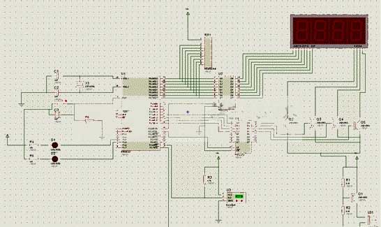
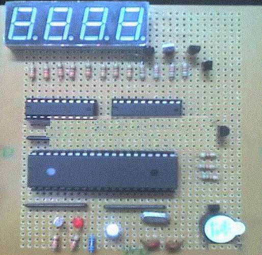
Because I was not very proficient in using buses at the time and was afraid of making mistakes, I connected them one by one. Moreover, only one exclusion was added to the schematic diagram, and the later modified diagram could not be found. The modified schematic adds two exclusion resistors, as shown in the circuit board! Later, when welding the actual object, the teacher bought four resistors, so he added a resistor to each interface of the microcontroller. The specific object is as shown in the actual picture!
The circuit board schematic diagram is as follows:
Because the model of the digital tube used is currently unknown, the schematic diagram of the digital tube is not drawn, but its position is marked:
Pictures of the final product are as follows:
The required components are as follows:
STC89C52RC (single chip microcomputer) one piece
One crystal oscillator (12MHZ)
Two ceramic capacitors (22PF) (for connecting to crystal oscillator)
Electrolytic capacitor (10uf) one
Resistors (330 ohms) 10
Resistor (4K7) one
Resistors (5K1) six
Resistor (10K) one
Exclusion (eight-bit 4K7) two
Light-emitting diodes (red, yellow) one each
74HC573 two
Transistor (2SA1015) five
Four-digit eight-segment common yang digital tube one
DS18B20 (temperature sensor) one
buzzer one
button one
 Experience summary:
The reason for choosing this topic is actually very simple. I have been studying microcontrollers for a while, but I have not had the opportunity to try to do something. And this electronic temperature alarm is not too difficult to make. This time it was just a good time to exercise my hands-on ability.
It can be said that this production was a failure. Although its function has been theoretically realized through simulation, it was only simulated on software, and the final product did not achieve the expected function! After making it, I carefully analyzed the production I designed and found that there were many unreasonable things. For example, the use of 74HC573, in fact, 74HC573 may not be useful in this production, because in my design, the LE and OE terminals of the latch are directly connected to the power supply terminal and the ground terminal. In this case, the latch is just regarded as a D flip-flop, which can be omitted! And those 330 ohm resistors. In fact, among the components, the resistor the teacher bought is 10K, and its current should be able to directly drive the digital tube. The 330 ohm resistor I added is based on the connection method on the development board, which is completely unnecessary for my design. These unreasonable points are mainly due to my lack of experience and my failure to carefully consider the selection of each component!
Overall, I definitely learned a lot through this production exercise. Such as the drawing and production of circuit boards, the drilling of circuit boards, the use of some common tools, and the correct selection of components when designing circuits. These will be very valuable for me when I am engaged in electronics career in the future!
In terms of alarm, when the temperature exceeds the maximum temperature of the alarm range, the alarm music will sound and the red LED will flash. When the temperature is lower than the minimum temperature alarm, the alarm music will sound and the yellow LED will flash! Because the selected microcontroller can be erased and written more than 10,000 times, in order to simplify the circuit, its temperature alarm value has been preset in the program. The alarm temperature can be changed by modifying the preset value in the program!
Because I was not very proficient in using buses at the time and was afraid of making mistakes, I connected them one by one. Moreover, only one exclusion was added to the schematic diagram, and the later modified diagram could not be found. The modified schematic adds two exclusion resistors, as shown in the circuit board! Later, when welding the actual object, the teacher bought four resistors, so he added a resistor to each interface of the microcontroller. The specific object is as shown in the actual picture!
The circuit board schematic diagram is as follows:
Because the model of the digital tube used is currently unknown, the schematic diagram of the digital tube is not drawn, but its position is marked:
Pictures of the final product are as follows:
The required components are as follows:
STC89C52RC (single chip microcomputer) one piece
One crystal oscillator (12MHZ)
Two ceramic capacitors (22PF) (for connecting to crystal oscillator)
Electrolytic capacitor (10uf) one
Resistors (330 ohms) 10
Resistor (4K7) one
Resistors (5K1) six
Resistor (10K) one
Exclusion (eight-bit 4K7) two
Light-emitting diodes (red, yellow) one each
74HC573 two
Transistor (2SA1015) five
Four-digit eight-segment common yang digital tube one
DS18B20 (temperature sensor) one
buzzer one
button one
The reason for choosing this topic is actually very simple. I have been studying microcontrollers for a while, but I have not had the opportunity to try to do something. And this electronic temperature alarm is not too difficult to make. This time it was just a good time to exercise my hands-on ability.
It can be said that this production was a failure. Although its function has been theoretically realized through simulation, it was only simulated on software, and the final product did not achieve the expected function! After making it, I carefully analyzed the production I designed and found that there were many unreasonable things. For example, the use of 74HC573, in fact, 74HC573 may not be useful in this production, because in my design, the LE and OE terminals of the latch are directly connected to the power supply terminal and the ground terminal. In this case, the latch is just regarded as a D flip-flop, which can be omitted! And those 330 ohm resistors. In fact, among the components, the resistor the teacher bought is 10K, and its current should be able to directly drive the digital tube. The 330 ohm resistor I added is based on the connection method on the development board, which is completely unnecessary for my design. These unreasonable points are mainly due to my lack of experience and my failure to carefully consider the selection of each component!
Overall, I definitely learned a lot through this production exercise. Such as the drawing and production of circuit boards, the drilling of circuit boards, the use of some common tools, and the correct selection of components when designing circuits. These will be very valuable for me when I am engaged in electronics career in the future!


