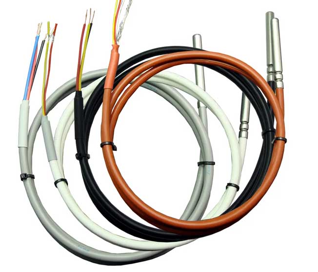
DS18B20 Temperature Sensor Probe and Cable
Introduction to DS18B20 temperature sensor:
DS18B20 is a digital temperature sensor with a wide range of applications. It outputs digital signals and has the characteristics of small size, low hardware resource consumption, strong anti-interference ability and high precision.

DS18B20 temperature sensor features:
1. Adopt single-wire interface method: DS18B20 temperature sensor only needs one wire to achieve two-way communication with the microprocessor.
2. Temperature measurement range: The temperature measurement range of DS18B20 temperature sensor can reach -55℃~+125℃, and the error is ±0.4° in the range of -10℃ to +85℃.
3. Support multi-point networking function: multiple DS18B20 temperature sensors can be connected in parallel on a data line, up to 8 can be connected in parallel to achieve multi-point temperature measurement.
4. Working power supply: 3.0~5.5V/DC. The DS18B20 temperature sensor can be powered by an external independent power supply or a data line parasitic power supply.
5. The DS18B20 temperature sensor does not require any external components during application.
6. The temperature measured by the DS18B20 temperature sensor is transmitted serially in a 9 to 12-bit digital format.
7. Power-down protection function. The DS18B20 temperature sensor contains an EEPROM inside. The digital conversion accuracy and alarm temperature can be set through the configuration register. The resolution and alarm temperature settings can still be saved after the DS18B20 temperature sensor is powered off.
8. The DS18B20 temperature sensor returns a 16-bit binary number representing the temperature value detected at this moment, and the high five digits represent positive and negative. If the high five bits are all 1, it means that the returned temperature value is a negative value. If the high five bits are all 0, it means that the returned temperature value is a positive value. The following 11 bits of data represent the absolute value of the temperature. After converting it to a decimal value, multiply it by 0.0625 to obtain the temperature value at this time.
DS18B20 temperature sensor pin description
DS18B20 temperature sensor parasitic power supply mode:
The parasitic power supply mode of the DS18B20 temperature sensor is shown in the figure below. In the parasitic power supply mode, the DS18B20 temperature sensor draws power from the signal line: when the signal line is high, the electric energy is stored in the internal capacitor. When the signal line is at a low level, the power on the capacitor is consumed, and the capacitor (parasitic power supply) is charged until the signal line reaches a high level.
Advantages of parasitic power supply:
1. No local power supply is required, and remote temperature measurement can be achieved.
2. Temperature measurement can be achieved with only one signal line, making the circuit simpler.
Disadvantages of parasitic power supply:
In order for the DS18B20 temperature sensor to perform accurate temperature conversion, the signal line must ensure that sufficient energy is provided during the temperature conversion. But when multiple DS18B20 temperature sensors are hung on the same signal line, the pull-up resistor alone cannot provide enough power, which will cause the DS18B20 temperature sensor to be unable to measure temperature or have a huge error.
Therefore, the parasitic power supply method is only suitable for use when measuring temperature with a single DS18B20 temperature sensor.
DS18B20 temperature sensor parasitic power supply strong pull-up power supply mode:
The strong pull-up power supply mode of the DS18B20 temperature sensor parasitic power supply is shown in the figure below. In order for the DS18B20 temperature sensor to obtain sufficient power supply during the temperature measurement process, use a MOSFET to directly pull the signal line to VCC to provide sufficient power. (Whenever copying or starting a temperature conversion command is involved, the signal line must be converted to a strong pull-up state within a maximum of 10μS) to solve the problem of insufficient power supply. The strong pull-up power supply mode of the DS18B20 temperature sensor parasitic power supply is suitable for multi-point temperature measurement applications, but it requires one more I/O line for strong pull-up switching.
External power supply mode of DS18B20 temperature sensor:
In the external power supply mode, the working power supply of the DS18B20 temperature sensor is connected to the VDD pin. There is no problem of insufficient power supply current and the conversion accuracy can be guaranteed. At the same time, multiple DS18B20 temperature sensors can be connected to the bus to form a multi-point temperature measurement system. The external power supply method is the best power supply method for the DS18B20 temperature sensor: it works stably and reliably, has strong anti-interference ability, and the circuit is relatively simple.
Internal structure of DS18B20 temperature sensor:
The interior of the DS18B20 temperature sensor is composed of 64-bit ROM, cache memory, CRC generator, temperature sensitive device, high and low temperature trigger and configuration register.
1. 64-bit ROM of DS18B20 temperature sensor
There is a 64-bit ROM inside the DS18B20 temperature sensor, and the ROM curing has certain contents. The lower eight bits (fixed to 28H) are the product type identification number, the next 48 bits are the serial number, and the upper eight bits are the previous 56 bits of cyclic redundancy check code.
2. Memory mapping of DS18B20 temperature sensor
There are 9-byte cache memory units in the DS18B20 temperature sensor, as shown in the figure below.
3. Configuration register of DS18B20 temperature sensor
The highest bit BIT7 of the configuration register byte of the DS18B20 temperature sensor is the test mode bit. It is 0 when shipped from the factory and does not need to be changed by the user. BIT6 and BIT5 are used to set the conversion resolution of the DS18B20 temperature sensor. There are four resolution options: 9, 10, 11 and 12 bits. The corresponding conversion times are: 93.73ms, 187.5ms, 375ms and 750ms respectively. The remaining 5 lower bits are reserved bits (all 1).
The default R0 and R1 settings of the DS18B20 temperature sensor are 11. That is 12-bit resolution, that is, 1 bit represents 0.0625 degrees Celsius.
Reading and writing of DS18B20 temperature sensor
instruction
The temperature value converted by the DS18B20 temperature sensor is stored in the 0th and 1st bytes of the high-speed temporary storage memory in two-byte complement form. So when we just want to simply read the temperature value, we only need to read the 0th and 1st bytes in the temporary register.
The simple steps to read the temperature value are as follows:
1. Skip ROM operation.
2. Send temperature conversion command.
3. Skip ROM operation.
4. Send the read temperature command.
5. Read the temperature value.
Initialization of DS18B20 temperature sensor
The master device first sends a low-level pulse of 480-960 microseconds, then releases the bus to high level, and detects the bus within the subsequent 480 microseconds. If there is a low level, it means that there is a DS18B20 temperature sensor on the bus that has responded. If there is no low level, it means that there is no response from the DS18B20 temperature sensor on the bus.
As a slave device, the DS18B20 temperature sensor has been detecting whether there is a low level of 480-960 microseconds on the bus as soon as it is powered on. If so, wait 15-60 microseconds after the bus turns high, then pull the bus level low for 60-240 microseconds to respond with a pulse, telling the host that the device is ready. If it is not detected, it will keep checking and waiting.
Write operation of DS18B20 temperature sensor:
The write cycle is a minimum of 60 microseconds and a maximum of 120 microseconds.
At the beginning of the write cycle, the master device first pulls the bus low for 1 microsecond to indicate the start of the write cycle. Then if the master wants to write a 0, it sets the bus low. If the master wants to write 1, it sets the bus high for at least 60 microseconds until the end of the write cycle, and then releases the bus high for at least 1 microsecond to allow the bus to recover. The DS18B20 temperature sensor waits for 15 microseconds after detecting that the bus is pulled down and then starts sampling the bus from 15us to 45us. It is 1 if the bus is high level during the sampling period, and 0 if the bus is low level during the sampling period.
Read operation of DS18B20 temperature sensor:
The read data operation timing is also divided into two processes: read 0 timing and read 1 timing.
The read cycle is when the master device pulls the single bus low for 1 microsecond and then releases the single bus to a high level to allow the DS18B20 temperature sensor to transmit data to the single bus. As a slave DS18B20 temperature sensor, it starts sending data after detecting that the bus is pulled low for 1 microsecond. If you want to send 0, pull the bus low until the end of the read cycle. If you want to send 1, release the bus to high level.
The master device initially pulls the bus low for 1 microsecond and then releases the bus, and then completes the sampling and detection of the bus within 15 microseconds including the previous 1 microsecond of pulling the bus level low. If the bus is low level during the sampling period, it is confirmed as 0. If the bus is high during the sampling period, it is confirmed as 1. It takes at least 60 microseconds to complete a read timing process.
DS18B20 temperature sensor application circuit
Single DS18B20 wiring method: VDD is connected to the power supply, DQ is connected to the microcontroller pin, a pull-up resistor is added, and GND is connected to ground. Note that this pull-up resistor is necessary, that is, the DQ pin must have a pull-up resistor.
A routine for DS18B20 temperature sensor
/******************DS18B20 measures temperature******************
*MCU model: STC89C52RC
*Development environment: KEIL
*Function: DS18B20 measures temperature and displays it in the digital tube
*************************************************/
#include <reg52.h>
#define uchar unsigned char
#define uint unsigned int
sbit DS = P2^2;
sbit LE1 = P2^6;
sbit LE2 = P2^7;
uint temp;
uchar flag1;
unsigned char code table[]={0x3f,0x06,0x5b,0x4f,0x66,0x6d,0x7d,0x07,0x7f,0x6f,0x77,0x7c,0x39,0x5e,0x79,0x71};
unsigned char code table1[]={0xbf,0x86,0xdb,0xcf,0xe6,0xed,0xfd,0x87,0xff,0xef};
void delay(uint count)
{
uint i;
while(count)
{
i=200;
while(i>0)
i--;
count--;
}
}
void dsreset(void)
{
uint i;
DS=0;
i=103;
while(i>0)i--;
DS=1;
i=4;
while(i>0)i--;
}
bit tmpreadbit(void)
{
uint i;
bit dat;
DS=0;i++;
DS=1;i++;i++;
dat=DS;
i=8;while(i>0)i--;
return (dat);
}
uchar tmpread(void)
{
uchar i,j,dat;
dat=0;
for(i=1;i<=8;i++)
{
j=tmpreadbit();
dat=(j<<7)|(dat>>1);
}
return(dat);
}
void tmpwritebyte(uchar dat)
{
uint i;
uchar j;
bit testb;
for(j=1;j<=8;j++)
{
testb=dat&0x01;
dat=dat>>1;
if(testb) //write 1
{
DS=0;
i++;i++;
DS=1;
i=8;while(i>0)i--;
}
else
{
DS=0;
i=8;while(i>0)i--;
DS=1;
i++;i++;
}
}
}
void tmpchange(void)
{
dsreset();
delay(1);
tmpwritebyte(0xcc);
tmpwritebyte(0x44);
}
uinttmp()
{
float tt;
uchar a,b;
dsreset();
delay(1);
tmpwritebyte(0xcc);
tmpwritebyte(0xbe);
a=tmpread();
b=tmpread();
temp=b;
temp<<=8;
temp=temp|a;
tt=temp*0.0625;
temp=tt*10+0.5;
return temp;
}
void display(uint temp)
{
uchar A1,A2,A2t,A3;
A1=temp/100;
A2t=temp%100;
A2=A2t/10;
A3=A2t%10;
LE1=0;
P0=table[A1]; //Display hundreds digit
LE1=1;
LE1=0;
LE2=0;
P0=0xfe;
LE2=1;
LE2=0;
delay(1);
LE1=0;
P0=table1[A2]; //Display tens digit
LE1=1;
LE1=0;
LE2=0;
P0=0xfd;
LE2=1;
LE2=0;
delay(1);
LE1=0;
P0=table[A3]; //Display units digit
LE1=1;
LE1=0;
LE2=0;
P0=0xfb;
LE2=1;
LE2=0;
delay(1);
}
void main()
{
uchar a;
do
{
tmpchange();
for(a=10;a>0;a--)
{
display(tmp());
}
} while(1);
}
DS18B20 is a digital temperature sensor with a wide range of applications. It outputs digital signals and has the characteristics of small size, low hardware resource consumption, strong anti-interference ability and high precision.
DS18B20 temperature sensor features:
1. Adopt single-wire interface method: DS18B20 temperature sensor only needs one wire to achieve two-way communication with the microprocessor.
2. Temperature measurement range: The temperature measurement range of DS18B20 temperature sensor can reach -55℃~+125℃, and the error is ±0.4° in the range of -10℃ to +85℃.
3. Support multi-point networking function: multiple DS18B20 temperature sensors can be connected in parallel on a data line, up to 8 can be connected in parallel to achieve multi-point temperature measurement.
4. Working power supply: 3.0~5.5V/DC. The DS18B20 temperature sensor can be powered by an external independent power supply or a data line parasitic power supply.
5. The DS18B20 temperature sensor does not require any external components during application.
6. The temperature measured by the DS18B20 temperature sensor is transmitted serially in a 9 to 12-bit digital format.
7. Power-down protection function. The DS18B20 temperature sensor contains an EEPROM inside. The digital conversion accuracy and alarm temperature can be set through the configuration register. The resolution and alarm temperature settings can still be saved after the DS18B20 temperature sensor is powered off.
8. The DS18B20 temperature sensor returns a 16-bit binary number representing the temperature value detected at this moment, and the high five digits represent positive and negative. If the high five bits are all 1, it means that the returned temperature value is a negative value. If the high five bits are all 0, it means that the returned temperature value is a positive value. The following 11 bits of data represent the absolute value of the temperature. After converting it to a decimal value, multiply it by 0.0625 to obtain the temperature value at this time.
DS18B20 temperature sensor pin description
DS18B20 temperature sensor parasitic power supply mode:
The parasitic power supply mode of the DS18B20 temperature sensor is shown in the figure below. In the parasitic power supply mode, the DS18B20 temperature sensor draws power from the signal line: when the signal line is high, the electric energy is stored in the internal capacitor. When the signal line is at a low level, the power on the capacitor is consumed, and the capacitor (parasitic power supply) is charged until the signal line reaches a high level.
Advantages of parasitic power supply:
1. No local power supply is required, and remote temperature measurement can be achieved.
2. Temperature measurement can be achieved with only one signal line, making the circuit simpler.
Disadvantages of parasitic power supply:
In order for the DS18B20 temperature sensor to perform accurate temperature conversion, the signal line must ensure that sufficient energy is provided during the temperature conversion. But when multiple DS18B20 temperature sensors are hung on the same signal line, the pull-up resistor alone cannot provide enough power, which will cause the DS18B20 temperature sensor to be unable to measure temperature or have a huge error.
Therefore, the parasitic power supply method is only suitable for use when measuring temperature with a single DS18B20 temperature sensor.
DS18B20 temperature sensor parasitic power supply strong pull-up power supply mode:
The strong pull-up power supply mode of the DS18B20 temperature sensor parasitic power supply is shown in the figure below. In order for the DS18B20 temperature sensor to obtain sufficient power supply during the temperature measurement process, use a MOSFET to directly pull the signal line to VCC to provide sufficient power. (Whenever copying or starting a temperature conversion command is involved, the signal line must be converted to a strong pull-up state within a maximum of 10μS) to solve the problem of insufficient power supply. The strong pull-up power supply mode of the DS18B20 temperature sensor parasitic power supply is suitable for multi-point temperature measurement applications, but it requires one more I/O line for strong pull-up switching.
External power supply mode of DS18B20 temperature sensor:
In the external power supply mode, the working power supply of the DS18B20 temperature sensor is connected to the VDD pin. There is no problem of insufficient power supply current and the conversion accuracy can be guaranteed. At the same time, multiple DS18B20 temperature sensors can be connected to the bus to form a multi-point temperature measurement system. The external power supply method is the best power supply method for the DS18B20 temperature sensor: it works stably and reliably, has strong anti-interference ability, and the circuit is relatively simple.
Internal structure of DS18B20 temperature sensor:
The interior of the DS18B20 temperature sensor is composed of 64-bit ROM, cache memory, CRC generator, temperature sensitive device, high and low temperature trigger and configuration register.
1. 64-bit ROM of DS18B20 temperature sensor
There is a 64-bit ROM inside the DS18B20 temperature sensor, and the ROM curing has certain contents. The lower eight bits (fixed to 28H) are the product type identification number, the next 48 bits are the serial number, and the upper eight bits are the previous 56 bits of cyclic redundancy check code.
2. Memory mapping of DS18B20 temperature sensor
There are 9-byte cache memory units in the DS18B20 temperature sensor, as shown in the figure below.
3. Configuration register of DS18B20 temperature sensor
The highest bit BIT7 of the configuration register byte of the DS18B20 temperature sensor is the test mode bit. It is 0 when shipped from the factory and does not need to be changed by the user. BIT6 and BIT5 are used to set the conversion resolution of the DS18B20 temperature sensor. There are four resolution options: 9, 10, 11 and 12 bits. The corresponding conversion times are: 93.73ms, 187.5ms, 375ms and 750ms respectively. The remaining 5 lower bits are reserved bits (all 1).
The default R0 and R1 settings of the DS18B20 temperature sensor are 11. That is 12-bit resolution, that is, 1 bit represents 0.0625 degrees Celsius.
Reading and writing of DS18B20 temperature sensor
instruction
The temperature value converted by the DS18B20 temperature sensor is stored in the 0th and 1st bytes of the high-speed temporary storage memory in two-byte complement form. So when we just want to simply read the temperature value, we only need to read the 0th and 1st bytes in the temporary register.
The simple steps to read the temperature value are as follows:
1. Skip ROM operation.
2. Send temperature conversion command.
3. Skip ROM operation.
4. Send the read temperature command.
5. Read the temperature value.
Initialization of DS18B20 temperature sensor
The master device first sends a low-level pulse of 480-960 microseconds, then releases the bus to high level, and detects the bus within the subsequent 480 microseconds. If there is a low level, it means that there is a DS18B20 temperature sensor on the bus that has responded. If there is no low level, it means that there is no response from the DS18B20 temperature sensor on the bus.
As a slave device, the DS18B20 temperature sensor has been detecting whether there is a low level of 480-960 microseconds on the bus as soon as it is powered on. If so, wait 15-60 microseconds after the bus turns high, then pull the bus level low for 60-240 microseconds to respond with a pulse, telling the host that the device is ready. If it is not detected, it will keep checking and waiting.
Write operation of DS18B20 temperature sensor:
The write cycle is a minimum of 60 microseconds and a maximum of 120 microseconds.
At the beginning of the write cycle, the master device first pulls the bus low for 1 microsecond to indicate the start of the write cycle. Then if the master wants to write a 0, it sets the bus low. If the master wants to write 1, it sets the bus high for at least 60 microseconds until the end of the write cycle, and then releases the bus high for at least 1 microsecond to allow the bus to recover. The DS18B20 temperature sensor waits for 15 microseconds after detecting that the bus is pulled down and then starts sampling the bus from 15us to 45us. It is 1 if the bus is high level during the sampling period, and 0 if the bus is low level during the sampling period.
Read operation of DS18B20 temperature sensor:
The read data operation timing is also divided into two processes: read 0 timing and read 1 timing.
The read cycle is when the master device pulls the single bus low for 1 microsecond and then releases the single bus to a high level to allow the DS18B20 temperature sensor to transmit data to the single bus. As a slave DS18B20 temperature sensor, it starts sending data after detecting that the bus is pulled low for 1 microsecond. If you want to send 0, pull the bus low until the end of the read cycle. If you want to send 1, release the bus to high level.
The master device initially pulls the bus low for 1 microsecond and then releases the bus, and then completes the sampling and detection of the bus within 15 microseconds including the previous 1 microsecond of pulling the bus level low. If the bus is low level during the sampling period, it is confirmed as 0. If the bus is high during the sampling period, it is confirmed as 1. It takes at least 60 microseconds to complete a read timing process.
DS18B20 temperature sensor application circuit
Single DS18B20 wiring method: VDD is connected to the power supply, DQ is connected to the microcontroller pin, a pull-up resistor is added, and GND is connected to ground. Note that this pull-up resistor is necessary, that is, the DQ pin must have a pull-up resistor.
A routine for DS18B20 temperature sensor
/******************DS18B20 measures temperature******************
*MCU model: STC89C52RC
*Development environment: KEIL
*Function: DS18B20 measures temperature and displays it in the digital tube
*************************************************/
#include <reg52.h>
#define uchar unsigned char
#define uint unsigned int
sbit DS = P2^2;
sbit LE1 = P2^6;
sbit LE2 = P2^7;
uint temp;
uchar flag1;
unsigned char code table[]={0x3f,0x06,0x5b,0x4f,0x66,0x6d,0x7d,0x07,0x7f,0x6f,0x77,0x7c,0x39,0x5e,0x79,0x71};
unsigned char code table1[]={0xbf,0x86,0xdb,0xcf,0xe6,0xed,0xfd,0x87,0xff,0xef};
void delay(uint count)
{
uint i;
while(count)
{
i=200;
while(i>0)
i--;
count--;
}
}
void dsreset(void)
{
uint i;
DS=0;
i=103;
while(i>0)i--;
DS=1;
i=4;
while(i>0)i--;
}
bit tmpreadbit(void)
{
uint i;
bit dat;
DS=0;i++;
DS=1;i++;i++;
dat=DS;
i=8;while(i>0)i--;
return (dat);
}
uchar tmpread(void)
{
uchar i,j,dat;
dat=0;
for(i=1;i<=8;i++)
{
j=tmpreadbit();
dat=(j<<7)|(dat>>1);
}
return(dat);
}
void tmpwritebyte(uchar dat)
{
uint i;
uchar j;
bit testb;
for(j=1;j<=8;j++)
{
testb=dat&0x01;
dat=dat>>1;
if(testb) //write 1
{
DS=0;
i++;i++;
DS=1;
i=8;while(i>0)i--;
}
else
{
DS=0;
i=8;while(i>0)i--;
DS=1;
i++;i++;
}
}
}
void tmpchange(void)
{
dsreset();
delay(1);
tmpwritebyte(0xcc);
tmpwritebyte(0x44);
}
uinttmp()
{
float tt;
uchar a,b;
dsreset();
delay(1);
tmpwritebyte(0xcc);
tmpwritebyte(0xbe);
a=tmpread();
b=tmpread();
temp=b;
temp<<=8;
temp=temp|a;
tt=temp*0.0625;
temp=tt*10+0.5;
return temp;
}
void display(uint temp)
{
uchar A1,A2,A2t,A3;
A1=temp/100;
A2t=temp%100;
A2=A2t/10;
A3=A2t%10;
LE1=0;
P0=table[A1]; //Display hundreds digit
LE1=1;
LE1=0;
LE2=0;
P0=0xfe;
LE2=1;
LE2=0;
delay(1);
LE1=0;
P0=table1[A2]; //Display tens digit
LE1=1;
LE1=0;
LE2=0;
P0=0xfd;
LE2=1;
LE2=0;
delay(1);
LE1=0;
P0=table[A3]; //Display units digit
LE1=1;
LE1=0;
LE2=0;
P0=0xfb;
LE2=1;
LE2=0;
delay(1);
}
void main()
{
uchar a;
do
{
tmpchange();
for(a=10;a>0;a--)
{
display(tmp());
}
} while(1);
}


