Circuit of Pt100 Temperature Sensor
Design, select and manufacture pt100 temperature sensor:
The pt100 temperature sensor is a sensor that converts temperature variables into a transmittable standardized output signal. Mainly used for measurement and control of temperature parameters in industrial processes. A transmitter with a sensor usually consists of two parts: the sensor and the signal converter. Sensors are mainly thermocouples or thermal resistors. The signal converter mainly consists of a measurement unit, a signal processing and a conversion unit (since industrial thermal resistors and thermocouple graduation meters are standardized, the signal converter is also called a transmitter when it is an independent product). Some transmitters have added display units, and some also have fieldbus capabilities.
Temperature is one of the physical parameters in nature that humans interact with most. Whether in production and experimental sites or residential and leisure sites, temperature collection or control is very frequent and important. Moreover, networked remote temperature collection and alarming are an inevitable trend in the development of modern science and technology. Since temperature is closely related to both the physical quantity itself and actual people's lives, temperature sensors will be produced accordingly.
Due to the relationship between temperature and resistance change of PT100 thermal resistor, people took advantage of this characteristic to invent and produce PT100 thermal resistor temperature sensor. It is an intelligent sensor integrating temperature and humidity collection. The temperature collection range can be from -200℃ to +850℃, and the humidity collection range is from 0% to 100%.
PT100 temperature sensor working circuit working principle
PT100 is a positive temperature coefficient thermistor. Speaking of what is a positive temperature coefficient? It must be combined with the negative temperature coefficient. As the temperature increases, the resistance of the resistor becomes larger, which is the thermistor with a positive temperature coefficient. On the contrary, if the resistance of the resistor becomes smaller as the temperature increases, it is a negative temperature coefficient thermistor.
The reason why PT100 is widely used is not only because of the wide temperature range it can measure (tens of degrees below zero to hundreds of degrees above zero), but also because of its very good linearity. "Linearity", to put it bluntly, means that for every one degree change in temperature, the resistance of the resistor increases by basically the same amount. In this way, our procedure is greatly simplified.
However, PT100 also has its shortcomings, that is, every time the temperature rises by one degree, the resistance change is too small, only 0.39 ohms. This requires hardware to provide high-precision and low-noise conversion.
There are many circuits circulating on the Internet, many of which cannot be used as products. Below I will provide you with a high-precision circuit, although the cost is a bit high, but the quality is good.
Regarding temperature measurement circuits, there are actually many things worth studying. Small circuits have great wisdom. For example, can you tell at a glance that this circuit cannot measure subzero temperatures? Can you calculate the range of temperatures this circuit can measure from what to how many degrees? Can you modify this circuit so that it can measure the temperature range you need? What will be the consequences if the inverting (-IN) and non-inverting (+IN) lines are exchanged?
Take a look. If you think the circuit is simple, can you answer all the questions above?
Circuit explanation:
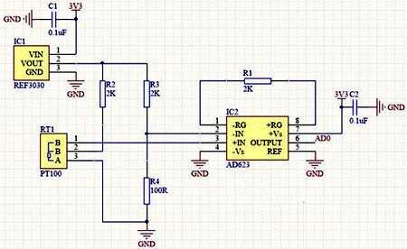
The simpler the circuit, the better the stability. The four resistors in this circuit all need to be 0.1% accurate. The circuit only uses a bridge and a differential amplifier. R2 R3 R4 and PT100 form a bridge circuit, and REF3030 provides a standard 3.00V voltage for the bridge circuit. AD623 uses a 2K amplification feedback resistor to accurately amplify the voltage difference of the bridge 51 times. (Why is it 51 times, please refer to the datasheet of AD623 for details)
PT100 connection method:
Careful friends will study the connection method of PT100. PT100 generally has two-wire and three-wire sensors. Because the wire itself must have resistance, and as mentioned above, for every degree of change, the PT100 only changes 0.39 ohms. So if the PT100 wire is very long, the resistance will be greater. Different wires will have different resistances, which will definitely greatly affect the measured results. So, you can understand now that the two-wire PT100 is only suitable for short-distance applications. For long-distance applications, a three-wire system must be used. Let us take a look at how the three-wire system eliminates the influence of resistance on the wire. Forget it, let’s talk about it in the next article. It takes a few pictures to explain this clearly. It’s getting late and I’m too lazy to draw.
Temperature measurement range:
Assuming it is 0 degrees now, then the resistance of PT100 is 100 ohms. In the circuit, the voltage difference across the bridge is 0V, so it ends up being 0V as well. In other words, if 0V is measured, it is 0 degrees. Assuming that it is now minus 1 degree, the resistance of PT100 is less than 100 ohms. The voltage in the same phase will be smaller than the voltage in the opposite phase, and the resulting voltage will always be 0V, so this circuit cannot measure below 0 degrees.
The maximum output voltage of AD623 is 3.3V, 3300/51=64.7mV. In other words, the voltage difference of the bridge can only be 64.7mV at maximum. No matter how large the voltage difference is, the maximum output of AD623 is 3.3V. The voltage of the inverting arm is fixed at (3000/2100)*100=142.86mV, then the maximum voltage of the non-inverting arm can only be 142.86+64.7=207.56mV, and the corresponding resistance of PT100 is equal to 207.56/((3000-207.56)/ 2000)=148.66 ohms.
Then look up the table and you can see that the maximum temperature measurement point is almost 127 degrees. Therefore, the temperature measurement range of this circuit is 0~127 degrees.
The pt100 temperature sensor is a sensor that converts temperature variables into a transmittable standardized output signal. Mainly used for measurement and control of temperature parameters in industrial processes. A transmitter with a sensor usually consists of two parts: the sensor and the signal converter. Sensors are mainly thermocouples or thermal resistors. The signal converter mainly consists of a measurement unit, a signal processing and a conversion unit (since industrial thermal resistors and thermocouple graduation meters are standardized, the signal converter is also called a transmitter when it is an independent product). Some transmitters have added display units, and some also have fieldbus capabilities.
Due to the relationship between temperature and resistance change of PT100 thermal resistor, people took advantage of this characteristic to invent and produce PT100 thermal resistor temperature sensor. It is an intelligent sensor integrating temperature and humidity collection. The temperature collection range can be from -200℃ to +850℃, and the humidity collection range is from 0% to 100%.
 |
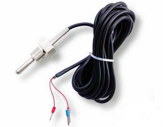 |
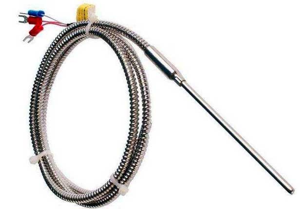
| 3-wire PT100 sensor circuit | Temperature control wiring method of PT100 |
PT100 temperature sensor working circuit working principle
PT100 is a positive temperature coefficient thermistor. Speaking of what is a positive temperature coefficient? It must be combined with the negative temperature coefficient. As the temperature increases, the resistance of the resistor becomes larger, which is the thermistor with a positive temperature coefficient. On the contrary, if the resistance of the resistor becomes smaller as the temperature increases, it is a negative temperature coefficient thermistor.
The reason why PT100 is widely used is not only because of the wide temperature range it can measure (tens of degrees below zero to hundreds of degrees above zero), but also because of its very good linearity. "Linearity", to put it bluntly, means that for every one degree change in temperature, the resistance of the resistor increases by basically the same amount. In this way, our procedure is greatly simplified.
However, PT100 also has its shortcomings, that is, every time the temperature rises by one degree, the resistance change is too small, only 0.39 ohms. This requires hardware to provide high-precision and low-noise conversion.
There are many circuits circulating on the Internet, many of which cannot be used as products. Below I will provide you with a high-precision circuit, although the cost is a bit high, but the quality is good.
Regarding temperature measurement circuits, there are actually many things worth studying. Small circuits have great wisdom. For example, can you tell at a glance that this circuit cannot measure subzero temperatures? Can you calculate the range of temperatures this circuit can measure from what to how many degrees? Can you modify this circuit so that it can measure the temperature range you need? What will be the consequences if the inverting (-IN) and non-inverting (+IN) lines are exchanged?
Take a look. If you think the circuit is simple, can you answer all the questions above?
Circuit explanation:
The simpler the circuit, the better the stability. The four resistors in this circuit all need to be 0.1% accurate. The circuit only uses a bridge and a differential amplifier. R2 R3 R4 and PT100 form a bridge circuit, and REF3030 provides a standard 3.00V voltage for the bridge circuit. AD623 uses a 2K amplification feedback resistor to accurately amplify the voltage difference of the bridge 51 times. (Why is it 51 times, please refer to the datasheet of AD623 for details)
PT100 connection method:
Careful friends will study the connection method of PT100. PT100 generally has two-wire and three-wire sensors. Because the wire itself must have resistance, and as mentioned above, for every degree of change, the PT100 only changes 0.39 ohms. So if the PT100 wire is very long, the resistance will be greater. Different wires will have different resistances, which will definitely greatly affect the measured results. So, you can understand now that the two-wire PT100 is only suitable for short-distance applications. For long-distance applications, a three-wire system must be used. Let us take a look at how the three-wire system eliminates the influence of resistance on the wire. Forget it, let’s talk about it in the next article. It takes a few pictures to explain this clearly. It’s getting late and I’m too lazy to draw.
Temperature measurement range:
Assuming it is 0 degrees now, then the resistance of PT100 is 100 ohms. In the circuit, the voltage difference across the bridge is 0V, so it ends up being 0V as well. In other words, if 0V is measured, it is 0 degrees. Assuming that it is now minus 1 degree, the resistance of PT100 is less than 100 ohms. The voltage in the same phase will be smaller than the voltage in the opposite phase, and the resulting voltage will always be 0V, so this circuit cannot measure below 0 degrees.
The maximum output voltage of AD623 is 3.3V, 3300/51=64.7mV. In other words, the voltage difference of the bridge can only be 64.7mV at maximum. No matter how large the voltage difference is, the maximum output of AD623 is 3.3V. The voltage of the inverting arm is fixed at (3000/2100)*100=142.86mV, then the maximum voltage of the non-inverting arm can only be 142.86+64.7=207.56mV, and the corresponding resistance of PT100 is equal to 207.56/((3000-207.56)/ 2000)=148.66 ohms.
Then look up the table and you can see that the maximum temperature measurement point is almost 127 degrees. Therefore, the temperature measurement range of this circuit is 0~127 degrees.


