Circuit Structure and Principle of Time Domain Temperature Sensor
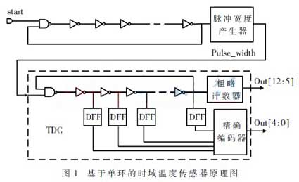
The time domain temperature sensor first needs to convert the temperature information into time information, and the ring oscillator is a way to convert the temperature into a time domain variable. According to the literature, the delay of the inverter has a linear relationship with the temperature. The frequency is finally measured into a digital code word by measuring the frequency with a Time-to-Digital Converter (TDC). To further improve accuracy, it is often necessary to calibrate the converted data. In addition, the calibration of the supply voltage can also be achieved by measuring the variance multiple times. The main circuit structure of a time domain temperature sensor based on a temperature compensated converter is shown in Figure 1.
1.1 Analysis and improvement of sensing circuit
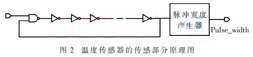
The sensing part of this design mainly uses the relationship between temperature and inverter delay to convert the temperature into the time variable pulse width pulse_width associated with it. Its circuit schematic is shown in Figure 2.
The delay of the inverter has the following quantitative relationship with the temperature:
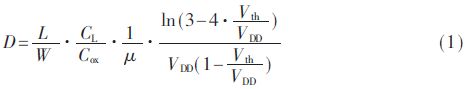
Where W and L are the width and length of the constituent transistors, respectively; CL and Cox are load capacitance and oxide layer capacitance per unit area; μ is the mobility of electrons (or holes); VDD and Vth are the supply voltage and the threshold voltage, respectively. It can be seen from the equation that the delay of the inverter is related to a plurality of parameters in which the mobility μ and the threshold voltage Vth are temperature-dependent. The change in transistor aspect ratio causes both threshold voltage and load capacitance changes, so choosing the right transistor size is especially important for the sensing portion. Compared to mobility, temperature causes a small and substantially linear relationship to the inverter delay by affecting the threshold voltage. Therefore, in the measurement range of 50 °C to 100 °C of interest in this paper, only the influence of temperature on mobility can be considered. The mobility has a negative temperature coefficient and its specific relationship is as follows:
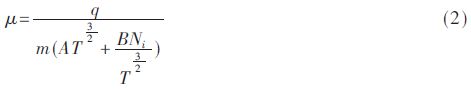 Where q is the charge of the electron (or hole); m is the effective quality; T is the temperature; Ni is the ionization impurity concentration; A and B are relative coefficients. It can be known from equation (1) that the inverter delay is inversely proportional to the mobility D∝1/μ; It can be seen from the formula (2) that the mobility is inversely proportional to the temperature μ∝1/T^a (where a is a constant [4] close to 1). It can be known from the literature that the frequency of the ring oscillator is F = 1 / (2ND), so the sensitivity of the frequency of the oscillation ring to temperature is inversely proportional to the aspect ratio of the transistor. Excessive oscillation frequency of the oscillation ring leads to large power consumption and causes a large self-heating effect, thus disturbing the measurement of the actual temperature. The Monte Carlo simulation method is used to obtain a reasonable width-to-length ratio of PMOS of L/W=0.3 μ/0.24 μ, because the electron mobility is about 2.5 times that of holes. In order to equalize the rise time and fall time of the inverter, the width to length ratio of the NMOS is L/W = 0.3 μ / 0.12 μ. Considering the oscillation frequency and the temperature coefficient, the ring oscillator composed of the 31-stage inverter is finally selected.
Time domain variables with temperature information can be obtained using the pulse width generator in the reference. According to equations (1) and (2), the width pulse_width of the pulse is a time variable related to temperature. From the quantitative analysis of the inverter and the temperature in the equations (1) and (2), the pulse width of the pulse is linear with the temperature within the measured temperature range. The nonlinear relationship between the oscillation frequency and the temperature of the oscillator composed of the inverters in series is the main cause of sensor measurement error. This design improves this problem by increasing the temperature coefficient of the oscillating ring frequency.
1.2 Analysis and improvement of time-to-digital converter
The ring oscillator of TDC is a key point of this design. Ideally, the TDC should be completely independent of temperature to reduce quantization error. However, TDC[2], which consists directly of standard gate-level units, has two problems—the first is that the frequency of the oscillation loop is very high, and the other is that the TDC oscillation itself is sensitive to temperature. Excessive oscillation frequency causes the oscillation ring to self-heat higher, which affects its own accuracy through temperature changes. If the size of the TDC oscillation delay unit is directly changed to reduce the oscillation ring frequency, the temperature coefficient is too large to increase the quantization error of the TDC. A TDC consisting directly of standard and gate units, in the high temperature range of more than 50 °C, may cause an excessively unacceptable error due to the above reasons. Therefore, this TDC is only suitable for use in the lower temperature range of 0 °C ~ 60 °C . This is the shortcoming of most existing related papers. How to improve this defect to make it more suitable for temperature measurement in the range of 50 ~ 100 °C is the main goal of the improvement of this design.
It has been explained in Section 1.1 that the oscillation frequency of the oscillating ring is related to the number of stages of the inverter and the delay of each stage of the inverter. When the number of stages of the inverter is smaller, the frequency of the oscillation ring is larger. In this design, in consideration of the self-heating problem of the circuit, it is generally desirable to have the frequency of the oscillation ring as low as possible. When the other conditions are constant, the frequency of the oscillation ring can be reduced by increasing the number of stages of the inverter. Since the standard cell delay is small, it takes a few hundred inverters to get the oscillation frequency that can be sampled by the counter, which is obviously unreasonable. Another way to change the oscillator frequency is to change the delay D of the inverter. As already mentioned, this will change the temperature coefficient of the oscillating ring, resulting in a temperature drift. Therefore, in order to reduce the temperature drift, the design introduces a current mirror unit capable of canceling the temperature coefficient of the inverter.
The TDC in this design uses a structure similar to the reference, as shown in the dashed box in Figure 1 as a schematic of the TDC. The 8-bit coarse counter counts the oscillator [12:5]. When the falling edge of pulse_width comes, the coarse counter stops counting, and the portion less than one counting period is tracked by the precision encoder and decoded into a 5-bit codeword. The result of the final quantization is the combination of the output of both the coarse counter and the exact encoder.
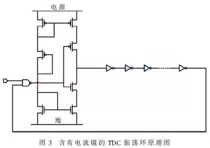
The basic idea of this paper is to use the temperature compensation of the current mirror to construct the oscillation ring of the TDC to eliminate the temperature drift of the TDC in the monitored temperature range. The current mirror works by compensating for the leakage current to change the charge and discharge time of the transistor, thereby changing the delay of the delay unit. The TDC oscillation ring with current mirror is shown in Figure 3. The simulation results are shown in Figure 4. It can be seen from the simulation results that the current mirror delay of this design has a negative temperature coefficient, and the delay of the inverter has a positive temperature coefficient within the measurement range. The results of Monte Carlo simulation can reasonably distribute the number of current mirror delay units and inverters, so that they have a small temperature drift in the monitored temperature range of 50 °C ~ 100 °C and the ideal result of acceptable oscillation frequency. The simulation results show that the oscillating ring of this structure can adjust the temperature range of temperature drift close to 0 to meet the application requirements according to the specific application and by changing the size of the inverter and the number of current mirrors. At the same time, the oscillation frequency of the structure is significantly reduced compared to the oscillation ring frequency composed of standard cells.
As shown in FIG. 4, TDC_ringx (x=1, 2, 3...) represents the cycle simulation result of the TDC oscillation ring under different parameters. The simulation results show that by adjusting different parameters, the delay unit with current mirror can offset the temperature drift of the inverter delay chain within a certain range. In this design, this range is determined to be 50 ° C to 100 ° C.
Since the oscillation of the oscillator will generate a certain degree of self-heating, the self-heating affects the accuracy of the temperature detection on the one hand, and brings irreversible influence on the circuit on the other hand, such as accelerating the aging of the circuit. When the oscillation frequency is too high, self-heating is particularly serious. Based on these problems, the design is designed to properly size the inverter in the TDC oscillating ring to reduce the frequency of the TDC oscillating ring, thereby reducing the self-heating of the circuit. In order to solve the problem that the temperature coefficient of TDC becomes large due to the change in the size of the inverter. A current mirror for temperature compensation is added to the oscillating ring of the TDC to bring the temperature drift of the TDC close to zero within the detection range, thereby enabling the sensor to meet the application requirements.
1.1 Analysis and improvement of sensing circuit
The sensing part of this design mainly uses the relationship between temperature and inverter delay to convert the temperature into the time variable pulse width pulse_width associated with it. Its circuit schematic is shown in Figure 2.
The delay of the inverter has the following quantitative relationship with the temperature:
Where W and L are the width and length of the constituent transistors, respectively; CL and Cox are load capacitance and oxide layer capacitance per unit area; μ is the mobility of electrons (or holes); VDD and Vth are the supply voltage and the threshold voltage, respectively. It can be seen from the equation that the delay of the inverter is related to a plurality of parameters in which the mobility μ and the threshold voltage Vth are temperature-dependent. The change in transistor aspect ratio causes both threshold voltage and load capacitance changes, so choosing the right transistor size is especially important for the sensing portion. Compared to mobility, temperature causes a small and substantially linear relationship to the inverter delay by affecting the threshold voltage. Therefore, in the measurement range of 50 °C to 100 °C of interest in this paper, only the influence of temperature on mobility can be considered. The mobility has a negative temperature coefficient and its specific relationship is as follows:
Time domain variables with temperature information can be obtained using the pulse width generator in the reference. According to equations (1) and (2), the width pulse_width of the pulse is a time variable related to temperature. From the quantitative analysis of the inverter and the temperature in the equations (1) and (2), the pulse width of the pulse is linear with the temperature within the measured temperature range. The nonlinear relationship between the oscillation frequency and the temperature of the oscillator composed of the inverters in series is the main cause of sensor measurement error. This design improves this problem by increasing the temperature coefficient of the oscillating ring frequency.
1.2 Analysis and improvement of time-to-digital converter
The ring oscillator of TDC is a key point of this design. Ideally, the TDC should be completely independent of temperature to reduce quantization error. However, TDC[2], which consists directly of standard gate-level units, has two problems—the first is that the frequency of the oscillation loop is very high, and the other is that the TDC oscillation itself is sensitive to temperature. Excessive oscillation frequency causes the oscillation ring to self-heat higher, which affects its own accuracy through temperature changes. If the size of the TDC oscillation delay unit is directly changed to reduce the oscillation ring frequency, the temperature coefficient is too large to increase the quantization error of the TDC. A TDC consisting directly of standard and gate units, in the high temperature range of more than 50 °C, may cause an excessively unacceptable error due to the above reasons. Therefore, this TDC is only suitable for use in the lower temperature range of 0 °C ~ 60 °C . This is the shortcoming of most existing related papers. How to improve this defect to make it more suitable for temperature measurement in the range of 50 ~ 100 °C is the main goal of the improvement of this design.
It has been explained in Section 1.1 that the oscillation frequency of the oscillating ring is related to the number of stages of the inverter and the delay of each stage of the inverter. When the number of stages of the inverter is smaller, the frequency of the oscillation ring is larger. In this design, in consideration of the self-heating problem of the circuit, it is generally desirable to have the frequency of the oscillation ring as low as possible. When the other conditions are constant, the frequency of the oscillation ring can be reduced by increasing the number of stages of the inverter. Since the standard cell delay is small, it takes a few hundred inverters to get the oscillation frequency that can be sampled by the counter, which is obviously unreasonable. Another way to change the oscillator frequency is to change the delay D of the inverter. As already mentioned, this will change the temperature coefficient of the oscillating ring, resulting in a temperature drift. Therefore, in order to reduce the temperature drift, the design introduces a current mirror unit capable of canceling the temperature coefficient of the inverter.
The TDC in this design uses a structure similar to the reference, as shown in the dashed box in Figure 1 as a schematic of the TDC. The 8-bit coarse counter counts the oscillator [12:5]. When the falling edge of pulse_width comes, the coarse counter stops counting, and the portion less than one counting period is tracked by the precision encoder and decoded into a 5-bit codeword. The result of the final quantization is the combination of the output of both the coarse counter and the exact encoder.
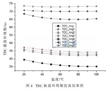
The basic idea of this paper is to use the temperature compensation of the current mirror to construct the oscillation ring of the TDC to eliminate the temperature drift of the TDC in the monitored temperature range. The current mirror works by compensating for the leakage current to change the charge and discharge time of the transistor, thereby changing the delay of the delay unit. The TDC oscillation ring with current mirror is shown in Figure 3. The simulation results are shown in Figure 4. It can be seen from the simulation results that the current mirror delay of this design has a negative temperature coefficient, and the delay of the inverter has a positive temperature coefficient within the measurement range. The results of Monte Carlo simulation can reasonably distribute the number of current mirror delay units and inverters, so that they have a small temperature drift in the monitored temperature range of 50 °C ~ 100 °C and the ideal result of acceptable oscillation frequency. The simulation results show that the oscillating ring of this structure can adjust the temperature range of temperature drift close to 0 to meet the application requirements according to the specific application and by changing the size of the inverter and the number of current mirrors. At the same time, the oscillation frequency of the structure is significantly reduced compared to the oscillation ring frequency composed of standard cells.
As shown in FIG. 4, TDC_ringx (x=1, 2, 3...) represents the cycle simulation result of the TDC oscillation ring under different parameters. The simulation results show that by adjusting different parameters, the delay unit with current mirror can offset the temperature drift of the inverter delay chain within a certain range. In this design, this range is determined to be 50 ° C to 100 ° C.
Since the oscillation of the oscillator will generate a certain degree of self-heating, the self-heating affects the accuracy of the temperature detection on the one hand, and brings irreversible influence on the circuit on the other hand, such as accelerating the aging of the circuit. When the oscillation frequency is too high, self-heating is particularly serious. Based on these problems, the design is designed to properly size the inverter in the TDC oscillating ring to reduce the frequency of the TDC oscillating ring, thereby reducing the self-heating of the circuit. In order to solve the problem that the temperature coefficient of TDC becomes large due to the change in the size of the inverter. A current mirror for temperature compensation is added to the oscillating ring of the TDC to bring the temperature drift of the TDC close to zero within the detection range, thereby enabling the sensor to meet the application requirements.


