6 Kinds of NTC Thermistor Temperature Measurement Circuit Diagram Daquan
Keywords: ntc thermistor, temperature measurement circuit
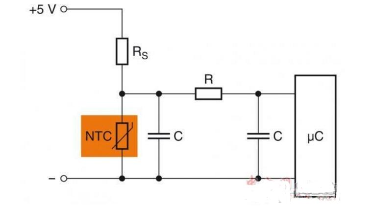
Thermistor Temperature Measurement Circuit Diagram of Microcontroller Thermal Protection (I)
To ensure proper operation of power semiconductor components, logic components, microcontrollers, and processors, overheating must be avoided. With its compact size (such as the EIA0402), the new SMDNTC thermistor can be placed directly adjacent to the microcontroller and other hotspots on the board. Since the solder joints form good thermal contact with the board and the self-heating of the components is minimal, the new thermistor enables high-precision temperature monitoring of semiconductor sensitive components. Due to the extremely high thermal shock resistance of EPCOS SMDNTC thermistors, this series of thermistors are suitable not only for reflow soldering but also for wave soldering. Designers can place thermistors on the underside of the board, such as the back of the microcontroller, ensuring excellent thermal contact even with large-size microcontrollers. The figure below shows a typical microcontroller protection circuit.
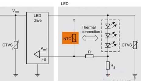
Ntc thermistor temperature measurement circuit diagram of LED lighting system (2)
In LED lighting systems, SMDNTC thermistors can help achieve higher luminous efficiency and extend the life of LEDs. The efficiency of the LED source is highly dependent on the temperature of the semiconductor junction. Because of the extreme temperature, the power degradation will be accelerated, the light intensity will be weakened, the color deviation and the service life will be significantly shortened, and even the LED system will be completely damaged. Too low a temperature will result in a decrease in luminous efficiency, which in turn will result in a decrease in the lumen value per volume unit, so the customer must try to avoid such a phenomenon. For maximum efficiency, the temperature must be within the specified optimum temperature range (typical for 70°C to 90°C for LED applications).If the SMDNTC thermistor is installed in the LED circuit, every change in the optimum operating temperature will cause a significant change in the resistance of the NTC component. After the comparator evaluation, the current flowing through the LED will be reduced, and the power loss of the LED will be reduced, thereby extending the service life. The figure below shows the corresponding circuit. We offer a sample kit with EPCOS SMDNTC thermistors for use by LED lighting system developers.
In addition to the standard series, we have also developed a car series. The new automotive series NTC thermistors are AEC-Q200 certified for applications up to +150 °C. It can be used in automotive electronic equipment such as ECUs, air conditioning systems, and battery temperature monitoring or charging systems.
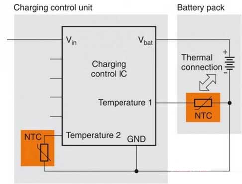
Ntc thermistor temperature measurement circuit diagram in fast charging pile (3)
Advanced charging technology not only requires the battery to have the highest allowable temperature, but also ensures that the charging current at the highest allowable temperature is lower than the maximum charging current of the battery. When the charging current causes the battery to reach the upper temperature limit, the rechargeable battery must reduce the current very accurately to avoid damage. The more accurate and rapid the battery temperature change detection, the more accurate and faster the charging current adjustment. This technology ensures that the battery is fully charged in the shortest amount of time and that the battery is not overheated.For applications such as fast charging, it is also necessary to measure the ambient temperature to avoid excessive temperature differences between the environment and the battery. To do this, the customer needs to place the second NTC thermistor directly on the charging board. The following figure shows such a typical circuit.
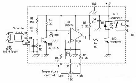
D-53 applied to ntc thermistor temperature measurement circuit diagram (4)
D-53 is the NTC thermistor temperature sensor (temperature sensor) 25 degrees resistance 5K temperature control range 0-150 degrees
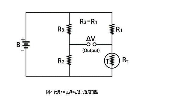
DC bridge circuit application ntc thermistor temperature measurement (5)
See the simple DC bridge circuit shown in the figure for precision measurements using thermistor manufacturers. The correct choice of resistors R2 and R3 will eliminate the average DC value of ΔV.
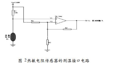
Ntc thermistor temperature measurement interface circuit diagram (6)
Fig. 2 is an interface circuit for temperature measurement of thermistor sensor using in-phase amplifier circuit. The interface circuit uses a resistor to linearize the thermistor sensor, and the interface circuit has a voltage mode and a resistance mode. The role of both is to achieve linearization. Figure 2 shows the linearization with a fixed resistor R1, called the voltage mode.
Resistor R1 pulls the thermistor's voltage up to the reference voltage, which is generally consistent with the ADC's reference voltage, so if the ADC's reference voltage is 5V, Vref will also be 5V. The thermistor and the resistor are connected in series to generate a partial voltage, and the resistance change causes the voltage V1 at the node to also change. The accuracy of this circuit depends on the error of the thermistor and resistor and the accuracy of the reference voltage.