Thermocouple Function and Application

What is a thermocouple sensor? The function, type and application of thermocouple
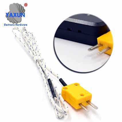
A thermocouple is a sensor for measuring temperature. It consists of two different metals joined at one end. When the union of the two metals is heated or cooled, a voltage is produced that can be correlated with temperature. Thermocouple alloys are commonly available in wire form.A thermocouple sensor is made up of two dissimilar metals bonded together at one end. The temperature is measured at this junction. The two metals generate a small voltage that can be measured and evaluated by a control system. The dissimilar metals are individually isolated and a sheath is used to maintain a tight bifilar configuration. (YAXUN) thermocouple sensors and assemblies are available in a variety of standard designs for a wide range of applications. Class 1 thermocouples are designed in accordance with IEC584. Custom thermocouple solutions are available. YAXUN has decades of experience in the development and manufacture of custom sensor solutions.
In principle, the thermocouple delivers electrical energy from heat at a temperature difference along the electrical conductor. The electrical voltage occurring at the other ends of the metallic conductor is comparatively small and is in the range of a few 10 µV per 1 ° C temperature difference. Even with high temperature differences above 1000 ° C and selected materials with high sensitivity, the achievable electrical voltages are below or in the order of magnitude of 0.1 V. Several thermocouples connected in series form a thermal chain, which supplies an electrical voltage that is higher by the number.
What are the different types of thermocouple?
A thermocouple is available in different combinations of metals or calibrations. The four most common calibrations are J, K, T, and E. There are high-temperature calibrations that are R, S, C, and GB. Each calibration has a different temperature and ambient range, although the maximum temperature varies with the diameter of the wire used in the thermocouple. Although the thermocouple calibration dictates the temperature range, the maximum range is also limited by the diameter of the thermocouple wire. That is, a very thin thermocouple may not reach the full temperature range. See a complete reference table (in English) for each thermocouple. The table includes international color codes for thermocouple alloys, temperature range, and limits of error for almost every kind of thermocouple.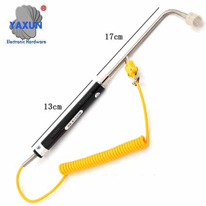
How do I choose a type of thermocouple?
Because a thermocouple measures wide temperature ranges and can be relatively rugged, thermocouples are used very frequently in industry. The following criteria are used to select a thermocouple:
Nickel-chromium / nickel (type K; most common type with thermal voltages between −6.458 mV at −270 ° C and 52.410 mV at 1300 ° C) with a sensitivity of about 40 µV / ° C (above 0 ° C)
Iron / copper-nickel (type J; for industrial applications with thermal voltages between −8.095 mV at −210 ° C and 69.553 mV at 1200 ° C) with slightly higher sensitivity, but less linear
Platinum-rhodium / platinum (types R and S; for high temperatures, up to approx. 20 mV) with a sensitivity of 5… 12 µV / ° C depending on the temperature
The positive conductor in each case is given first; it has a positive potential compared to the other conductor at a positive temperature difference at which the measuring point is warmer than the reference point.
In addition, two high-purity thermocouples gold-platinum and platinum-palladium are standardized, but their handling is difficult.
Temperature range
Chemical resistance of thermocouple or sheath material
Resistance to abrasion and vibration
Installation requirements (may need to be compatible with existing equipment; existing holes could determine probe diameter)
For the measurement of high temperatures, standardization has been expanded to include tungsten-based thermocouples up to 2500 ° C. Gold-based thermocouples have been developed for measuring low temperatures, but their thermal voltages are not (yet) sufficiently reproducible for uniform definition.
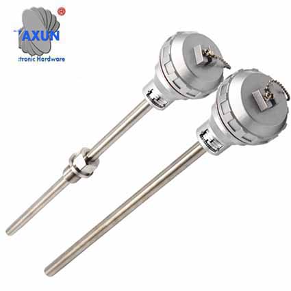
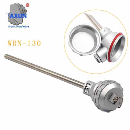
To protect against contaminating, corrosive or abrasive influences from the environment, thermocouples are manufactured for industrial use as sheathed thermocouples or as measuring inserts with a protective tube. The measuring insert is operated in an outer protective tube with a connection head for easy interchangeability - even during operation.
How do I know which type of union to choose?
Sheathed thermocouple probes are available with one of three types of junction: grounded, ungrounded, or exposed. At the tip of a ground bonding probe, the thermocouple wires are physically attached to the inside of the probe wall. This produces good heat transfer from the outside, through the probe wall to the thermocouple junction. In an ungrounded probe, the thermocouple junction is separated from the probe wall. Response time is slower than grounded style, but unconnected style offers electrical isolation (see table below).|
Insulation resistance at room temperature Ungrounded thermocouple |
||
| Nominal sheath diameter | DC voltage applied min. | Insulation resistance min. |
| Menos de 0.90 mm (0.03 pulg.) | 50 V | 100 M Ohmios |
| 0.80-1.5 mm (0.030 a 0.059 pulg.) | 50 V | 500 M Ohmios |
| Mayor de 1.5 mm (0.059 pulg.) | 500 V | 1000 M Ohmios |
The thermocouple in the exposed junction style exits the tip of the sheath and is exposed to the surrounding environment. This type offers the best response time, but is limited to use in dry, non-corrosive, and non-pressurized applications.
What is the response time?
A time constant is defined as the time it takes for a sensor to achieve 63.2% of a step change in temperature under a specified set of conditions. Five time constants are required for the sensor to approach 100% of the pitch change value. An exposed junction thermocouple is the fastest responding. Also, the smaller the diameter of the probe sleeve, the faster the response, but the maximum temperature may be lower. Keep in mind, however, that sometimes the probe sleeve cannot withstand the full temperature range of the thermocouple type.| Material | Maximum temperature | Application atmosphere | |||
| Oxidant | Hydrogen | Empty | Inert | ||
| 304 stainless steel | 900 °C (1650 °F) | Very good | Good | Very good | Very good |
| Inconel 600 | 1148 °C (2100 °F) | Very good | Good | Very good | Very good |
Thermocouple error ranges and limits
The following table shows the temperature and accuracy ranges for types J, K, E, and T thermocouples. Additional thermocouple types.
Common Thermocouple Temperature Ranges Chart
Common Thermocouple Temperature Ranges Chart
Thermocouple Type Reference Tables
The thermocouple produces a voltage output that can be correlated to the temperature that the thermocouple is measuring. The documents in the table below provide the thermoelectric voltage and corresponding temperature for a given thermocouple type. Most documents also provide the thermocouple temperature range, error limits, and environmental factors.
Comparison of different thermocouples
The following table gives characteristic data (largely from) and the identification of different types of thermocouples.Because of the expected drift, it is recommended to maintain an upper operating temperature that is dependent on the wire diameter. For types K, J, N, E, T, a continuous service life of 10,000 h in clean air is expected, for the precious metal types R, S, B of 2,000 h. With the information in brackets, a shortened service life of 250 h or 50 h is expected.
In the information on the limit deviation, t stands for the Celsius temperature of the measuring point. Of the two items of information, the larger of the two applies, namely as an indication of the amount. For example, a thermocouple with the specification "1.5 ° C or 0.004 · | t |" can measure the temperature at 1000 ° C with a deviation of −4 ° C or up to +4 ° C. The guaranteed limit deviations only apply to thermowires marked as belonging together in the delivery condition.
| Type | materials |
applicable to ... ° C |
Are defined from ... to ... ° C |
Limit deviation in class 1 |
Limit deviation in class 2 |
| K | NiCr-Ni |
750 – 1100 (850 – 1200) |
−270 to +1300 |
1,5 °C or 0,004·|t| in −40 to 1000 °C |
2,5 °C or 0,0075·|t| in −40 to 1200 °C |
| J | Fe-CuNi |
400 – 600 (500 – 750) |
−210 to +1200 |
1,5 °C or 0,004·|t| in −40 to 750 °C |
2,5 °C or 0,0075·|t| in −40 to 750 °C |
| N | NiCrSi-NiSi |
850 – 1200 (900 – 1250) |
−270 to +1300 |
1,5 °C or 0,004·|t| in −40 to 1000 °C |
2,5 °C or 0,0075·|t| in −40 to 1200 °C |
| E | NiCr-CuNi |
440 – 690 (480 – 800) |
−270 to +1000 |
1,5 °C or 0,004·|t| in −40 to 800 °C |
2,5 °C or 0,0075·|t| in −40 to 900 °C |
| T | Cu-CuNi |
200 – 300 (250 – 350) |
−270 to +400 |
0,5 °C or 0,004·|t| in −40 to 350 °C |
1 °C or 0,0075·|t| in −40 to 350 °C |
| R | Pt13Rh-Pt |
1400 (1600) |
−50 to +1768 |
1 °C in 0 to 1100 °C or 1 °C + 0,003·(t−1100 °C) in 1100 to 1600 °C |
1,5 °C or 0,0025·t in 0 to 1600 °C |
| S | Pt10Rh-Pt |
1400 (1600) |
−50 to +1768 |
1 °C in 0 to 1100 °C or 1 °C + 0,003·(t−1100 °C) in 1100 to 1600 °C |
1,5 °C or 0,0025·t in 0 to 1600 °C |
| B | Pt30Rh-Pt6Rh |
1500 (1700) |
0 to +1820 | – - - |
1,5 °C or 0,0025·t in 600 to 1700 °C |
| C | W5Re-W26Re | 0 to 2315 | – - - |
0,01·t in 426 to 2315 °C |
|
| A | W5Re-W20Re | 0 to 2500 | – - - |
0,01·t in 1000 to 2500 °C |
|
| AuFe-NiCr | −272 – +300 | not available | Reproducible send 0.2% of the voltage; each Senso must be individually calibrated. | ||
The order states of NiCr-Ni thermocouples
In the case of NiCr-Ni thermocouples, different states of order arise, which are caused by the temperature and cooling rate of the NiCr alloy. In this context, one speaks of the K-state (ordered state) and the U-state (disordered state). In both states, the thermocouple generates a reproducible thermal voltage, but the deviations from one another can be up to 5 K. The NiCr alloy has a face-centered cubic crystal lattice. In the K state, chromium atoms form the corners and the nickel atoms are in the center of the surfaces. This state always occurs at temperatures above 600 ° C. If the thermocouple is allowed to cool down at a rate of more than 100 K / h in the range of 600 ... 400 ° C, this will result in "disturbances" in the crystal lattice. H. Nickel atoms at the corners of the structure and chromium atoms in the center. This arrangement is known as the U-state. At higher cooling rates, the atoms do not have time to break out of the ordered state. However, since temperature is a very sluggish quantity in metrological practice, NiCr-Ni thermocouples usually cool down too slowly, and the K state occurs below 600 ° C. This effect can be minimized by adding silicon to the extent that it is negligible in terms of measurement technology. This has been implemented with the thermocouple type N, NiCrSi-NiSi, which, however, is only slowly finding its way into metrological practice.Applications : temperature measurement
Temperature differenceWith a measuring circuit - as in the picture above in the basics - three different material combinations arise through transitions to copper conductors: A → B, B → Cu, Cu → A. At the same temperature at both connection terminals, the copper potential drops out of the calculation, and what remains at this point is the potential difference of the combination B → A. In this way, the connection terminals take on the function of the comparison point. The reference junction can be relocated to a more distant location by means of so-called extension cables or compensating cables, e.g. B. in industrial plants up to the control room. These extension cables are made of identical thermal materials and the compensating cables are made of cheaper materials that have the same thermoelectric properties as the thermocouple itself over a limited temperature range.
Temperature instead of temperature difference
Since only a temperature difference can be determined with the aid of a thermocouple, a cold junction compensation (CJC) is necessary to measure the temperature. In the simplest case, the temperature at the transition point (the reference junction temperature) must be known; The temperature difference for the measured thermal voltage is read off in a table; this is added to the reference junction temperature. This procedure can only be used if a linear approximation is permissible.
For many measurement purposes, the relationship between thermal voltage and temperature difference is not sufficiently linear. Before using the table, note the reference temperature from which the table is calculated (0 mV mostly at 0 ° C). If there is a difference between the reference junction temperature and the reference temperature, the measured voltage must be corrected before using the table by the table value of the voltage that corresponds to the reference junction temperature. In the case of a curved characteristic, the following rule applies to the inclusion of the comparison point:
The addition of partial voltages correctly leads to the total voltage. The addition of the associated table values of the partial temperatures does not lead to the total temperature!
The thermal voltage can be processed by a suitable amplifier in order to be able to distribute it resiliently. Commercially available measuring transducers amplify, also take into account the (variable) reference junction temperature and linearize the output signal and temperature for a specified reference junction temperature (temperature-linear instead of voltage-linear output signal).


