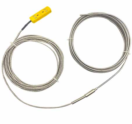
Armoured thermocouple sensor for boiler and furnace wall
1. Application of thermocouples for boilers and furnace walls
When installing the armored thermocouple on the metal wall of the boiler, the installation position of the armored thermocouple should be selected. There are several ways to install a thermocouple with a boiler metal wall armor. The installation method of armored thermocouple should be selected according to the specific situation of the site. The installer should compare the performance of these installation methods. Choose the installation method of the armored thermocouple according to the use requirements and performance comparison.Boiler metal temperature is an important parameter in operation. The upper and lower parts of the drum wall, The wall of the steam drum guide tube, Reheater tube wall, The outer wall of the sleeve of the burner throat and the wall of the front end of the primary air nozzle are required to be installed with armored thermocouples. The measurement parameters are particularly important to ensure the safe operation of the steam drum and superheater, and to understand the uniformity and stability of the furnace flame combustion and whether the burner is overheated. The prone fault of thermocouple is the disconnection or short circuit of the lead wire of the temperature measuring element, and the fault can be dealt with after stopping the boiler. Therefore, the correct installation method should be selected to ensure the installation quality, so that the unit can operate stably and effectively.
Selection of the installation position of the armored thermocouple
The boiler manufacturer has detailed regulations on the location of measurement points for armored thermocouples based on the thermal performance of the boiler. It can be installed according to the location given by the manufacturer's drawings. If the manufacturer does not give the elevation of the measuring point. For the superheater and reheater tube wall measurement points are generally taken on the vertical tube section within 100mm from the top of the D shed tube (if the height is not suitable, it can be adjusted appropriately). The installation height of the measuring points on the same superheater and reheater tube bank should be the same. The measuring points on the drum wall can be divided equally according to their geometric lines.2. Technical parameter table
| Thermocouple index number | Temperature measuring element | Diameter size | Operating temperature | Material of outer sheath | Length of armor L | Lead wire S | Insulation resistance value |
| K or E | Recommend double | Φ3 or Φ4 | 0~600℃ | 1Cr18Ni9Ti or 316 | Maximum length<120M | Recommend 2M |
20℃时,>1000MΩ/500VDC 500℃时,>5MΩ/500VDC *660℃时,>5MΩ/500VDC |
| Recommend Φ5 or Φ6 | 0~800℃ | ||||||
|
Note: 1. The insulating layer of the sheathed thermocouple has limited conductivity. The insulation resistance value decreases as the length of the sheathed thermocouple increases, so the conductivity of the sheathed thermocouple is represented by Sm-1 (equal to Ω-1*m-1). Therefore, the minimum insulation resistance of an armored thermocouple with a length greater than 1m is expressed in Ω*m or MΩ*m, and the minimum insulation resistance is expressed in MΩ when the length is less than 1M; 2. "*" Other requirements are selected, please indicate when ordering. |
|||||||
Type of armored thermocouple for boiler M
| W | Thermometers | ||||||
| R | Thermocouple | ||||||
| □ | Material of temperature sensing element | ||||||
| K | Nickel Chromium-Nickel Silicon | ||||||
| E | Nickel Chromium-Constantan | ||||||
| K | Armor type | ||||||
| □ | Number of thermocouple wire pairs | ||||||
| 1 | Single thermocouple (can be omitted) | ||||||
| 2 | Double thermocouple | ||||||
| -□ | Thermocouple category | ||||||
| 131 | Non-fixed, waterproof armored thermocouple | ||||||
| 191 | Compensation wire type | ||||||
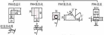
| /□ | Installation form of heat collector | ||||||
| PD01 | Temperature sensor 20*25mm | ||||||
| PD02 | Temperature sensor 20*75mm | ||||||
| PD03 | Fixed card | ||||||
| PD04 | R arc of heat collecting block | ||||||
| PD05 | R-arc bevel heat collecting block | ||||||
| PD06 | Square heat collector + base | ||||||
| W | R | K | K | -131 | /PD04 | WRKK-131/PD04 | |
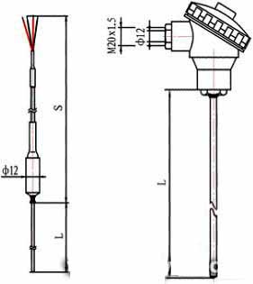
4. Outline structure drawing of boiler and furnace wall thermocouple