PT100 RTD Temperature Sensor Probe


- PRODUCT DETAIL
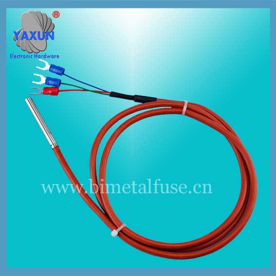
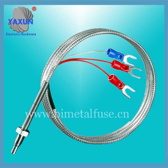
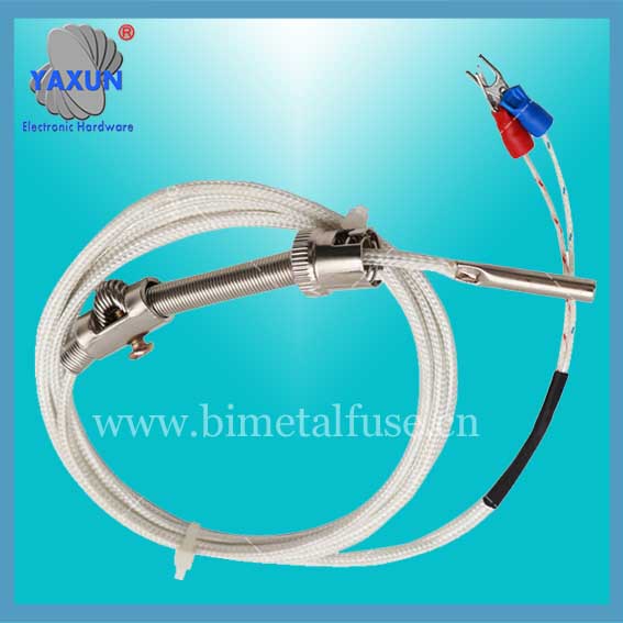
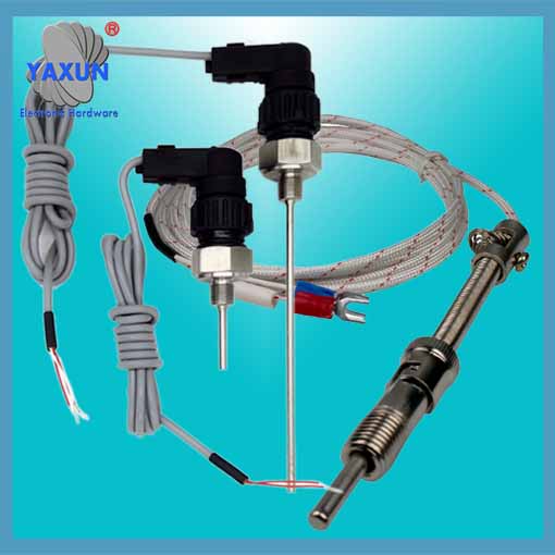
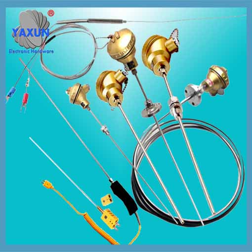
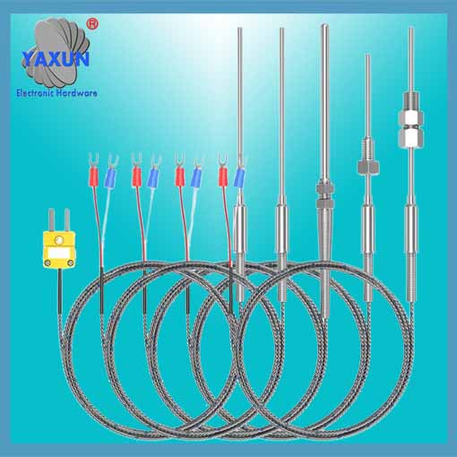
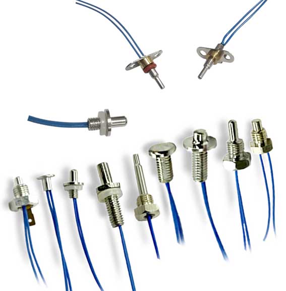
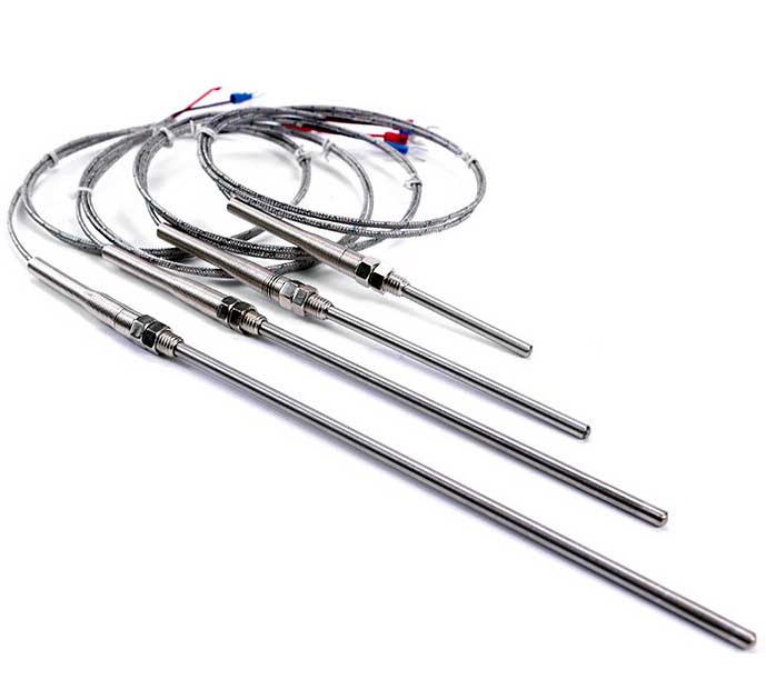
A Resistance Temperature Detector (PT100 RTD) is a sensor used to measure temperature by changing resistance proportionally to temperature. The PT100 RTD is designed with a basic temperature element and a complete probe and wiring harness assembly. These so-called RTD probes consist of an RTD sensor element, a sheath or housing, epoxy or filler material, extension leads, and sometimes a connector or termination. Different sensor materials can be used based on customer requirements for material compatibility, accuracy and measurement range. Standard kits and custom designs provide the flexibility to design the most suitable RTD temperature sensor for many different applications.
PT100 RTD temperature sensors and probes can be integrated into a variety of applications across a variety of industries. These temperature sensors are certified by multiple agencies to operate on board-mounted pressure components; they can also operate in harsh and hazardous environments. Our broad range of temperature sensor product options address the specific sensing needs of demanding OEM applications including medical, aerospace, automotive, instrumentation, home appliances, motor control and HVAC and refrigeration systems.
 What is a PT100 RTD sensor?
An RTD (Resistance Temperature Detector) is a sensor whose resistance changes with changes in temperature. Its resistance increases as the sensor temperature increases. The relationship between resistance and temperature is well known and repeatable over time. RTD is a passive device. It does not produce output by itself. External electronics can be used to measure the sensor resistance by passing a small current through the sensor to produce a voltage. Typically 1 mA or less measurement current, maximum 5 mA, without risk of self-heating.
 PT100 RTD standard tolerances
RTDs are built to several standardized curves and tolerances. The most commonly used normalized curve is the "DIN" curve. This curve describes the resistance versus temperature characteristics of platinum with a 100 ohm sensor, standardized tolerances, and measurable temperature range.
The DIN standard specifies a base resistance of 100 ohms at 0°C and a temperature coefficient of 0.00385 ohms/ohms/°c. The nominal output of DIN RTD sensors is as follows:
DIN RTD has three standard tolerance classes. These tolerances are defined as follows:
DIN Class A: ±(0.15 + 0.002 |T|°C)
DIN Class B: ±(0.3 + 0.005 |T|°C)
DIN Class C: ±(1.2 + 0.005 |T|°C)
0°C/ ohms
0: 100.00
10: 103.90
20: 107.79
30: 111.67
40: 115.54
50: 119.40
60: 123.24
70: 127.07
80: 130.89
90: 134.70
100: 138.50
 RTD component type
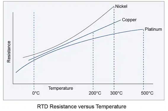
When determining the type of RTD element, first consider the instrument used to read the sensor. Select a component type that is compatible with the instrument's sensor input. By far the most commonly used RTD is 100 ohm platinum with a temperature coefficient of 0.00385.
Component Type Base Resistor (ohms) TCR (ohms/ohms/°C)
Platinum 100 ohms at 0°C .00385
Platinum 100 ohms at 0°C .00392
Platinum 100 ohms at 0°C .00375
Nickel 120 ohms at 0°C .00672
Copper 10 ohms at 25°C .00427
RTD accuracy
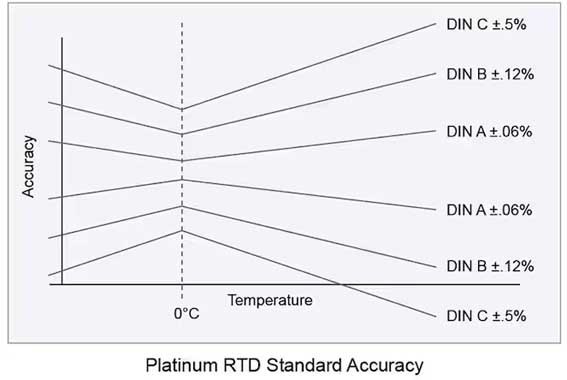 Second, determine the required measurement accuracy. Accuracy is a combination of the base resistor tolerance (resistance tolerance at calibration temperature) and the resistor tolerance temperature coefficient (characteristic slope tolerance). Any temperature above or below this will have a wider tolerance band or less accuracy (see figure below). The most commonly used calibration temperature is 0°C.
Sensor connection
The PT100 RTD sensor is available in several different lead configurations. The most common configuration is the single-element three-lead configuration. A schematic of the available lead configurations is shown below:
PT100/PT1000 two-wire sensors are typically used in applications where accuracy is not important. A two-wire configuration enables the simplest measurement technique, but has inherent inaccuracies due to the resistance of the sensor leads. In a two-wire configuration, it is not possible to directly compensate for the lead resistance that causes increased offset in the resistance measurement.
The PT100/PT1000 three-wire sensor has a compensation loop that can eliminate lead resistance during measurement. With this configuration, the controller/measuring device can take two measurements. For the first measurement, measure the total resistance of the sensor and connecting leads. During the second measurement, measure the resistance of the compensation loop resistor. The actual net resistance is determined by subtracting the compensation loop resistance from the total resistance. Three-wire sensors are the most common configuration and offer a good combination of accuracy and convenience.
PT100/PT1000 four-wire sensor configuration and measurement technology measures sensor resistance without being affected by the leads. While this technique is more accurate, many industrial controllers/measurement devices are unable to achieve true four-wire measurements.
The transition from sensor leads to field wiring is usually done at the connector that connects to the sensor. Terminal blocks are provided for easy connection.
Impact of Sensor Lead Options
Measuring temperature with a resistance temperature detector is actually measuring resistance. An unbalanced Wheatstone bridge is often used to measure resistance. When measuring the resistance of a sensing element, all external factors must be minimized or compensated for in order to obtain an accurate reading.
One major cause of errors can be the resistance of the leads, especially in a two-lead configuration.
The resistor is in series with the sensing element, so the reading is the sum of the sensing element and lead resistance. Two-lead RTDs can be used when the resistance of the sensing element is high and the resistance of the leads is low.
However, when the resistance of the leads is relatively high, it must be compensated. Compensation is available in a three-lead configuration. As shown in the three-lead diagram, one side of the power supply is connected to one side of the RTD through L3. This puts L1 and L2 on opposite sides of the bridge, so they cancel each other out and have no effect on the bridge output voltage.
It is recommended to use a three-lead connection for RTDs, especially if the sensing element resistance is low, where a small lead resistance can have a large impact on the accuracy of the reading.
PT100 RTD temperature sensors and probes can be integrated into a variety of applications across a variety of industries. These temperature sensors are certified by multiple agencies to operate on board-mounted pressure components; they can also operate in harsh and hazardous environments. Our broad range of temperature sensor product options address the specific sensing needs of demanding OEM applications including medical, aerospace, automotive, instrumentation, home appliances, motor control and HVAC and refrigeration systems.
An RTD (Resistance Temperature Detector) is a sensor whose resistance changes with changes in temperature. Its resistance increases as the sensor temperature increases. The relationship between resistance and temperature is well known and repeatable over time. RTD is a passive device. It does not produce output by itself. External electronics can be used to measure the sensor resistance by passing a small current through the sensor to produce a voltage. Typically 1 mA or less measurement current, maximum 5 mA, without risk of self-heating.
RTDs are built to several standardized curves and tolerances. The most commonly used normalized curve is the "DIN" curve. This curve describes the resistance versus temperature characteristics of platinum with a 100 ohm sensor, standardized tolerances, and measurable temperature range.
The DIN standard specifies a base resistance of 100 ohms at 0°C and a temperature coefficient of 0.00385 ohms/ohms/°c. The nominal output of DIN RTD sensors is as follows:
DIN RTD has three standard tolerance classes. These tolerances are defined as follows:
DIN Class A: ±(0.15 + 0.002 |T|°C)
DIN Class B: ±(0.3 + 0.005 |T|°C)
DIN Class C: ±(1.2 + 0.005 |T|°C)
0°C/ ohms
0: 100.00
10: 103.90
20: 107.79
30: 111.67
40: 115.54
50: 119.40
60: 123.24
70: 127.07
80: 130.89
90: 134.70
100: 138.50
When determining the type of RTD element, first consider the instrument used to read the sensor. Select a component type that is compatible with the instrument's sensor input. By far the most commonly used RTD is 100 ohm platinum with a temperature coefficient of 0.00385.
Component Type Base Resistor (ohms) TCR (ohms/ohms/°C)
Platinum 100 ohms at 0°C .00385
Platinum 100 ohms at 0°C .00392
Platinum 100 ohms at 0°C .00375
Nickel 120 ohms at 0°C .00672
Copper 10 ohms at 25°C .00427
RTD accuracy
Sensor connection
The PT100 RTD sensor is available in several different lead configurations. The most common configuration is the single-element three-lead configuration. A schematic of the available lead configurations is shown below:
PT100/PT1000 two-wire sensors are typically used in applications where accuracy is not important. A two-wire configuration enables the simplest measurement technique, but has inherent inaccuracies due to the resistance of the sensor leads. In a two-wire configuration, it is not possible to directly compensate for the lead resistance that causes increased offset in the resistance measurement.
The PT100/PT1000 three-wire sensor has a compensation loop that can eliminate lead resistance during measurement. With this configuration, the controller/measuring device can take two measurements. For the first measurement, measure the total resistance of the sensor and connecting leads. During the second measurement, measure the resistance of the compensation loop resistor. The actual net resistance is determined by subtracting the compensation loop resistance from the total resistance. Three-wire sensors are the most common configuration and offer a good combination of accuracy and convenience.
PT100/PT1000 four-wire sensor configuration and measurement technology measures sensor resistance without being affected by the leads. While this technique is more accurate, many industrial controllers/measurement devices are unable to achieve true four-wire measurements.
The transition from sensor leads to field wiring is usually done at the connector that connects to the sensor. Terminal blocks are provided for easy connection.
Impact of Sensor Lead Options
Measuring temperature with a resistance temperature detector is actually measuring resistance. An unbalanced Wheatstone bridge is often used to measure resistance. When measuring the resistance of a sensing element, all external factors must be minimized or compensated for in order to obtain an accurate reading.
One major cause of errors can be the resistance of the leads, especially in a two-lead configuration.
The resistor is in series with the sensing element, so the reading is the sum of the sensing element and lead resistance. Two-lead RTDs can be used when the resistance of the sensing element is high and the resistance of the leads is low.
However, when the resistance of the leads is relatively high, it must be compensated. Compensation is available in a three-lead configuration. As shown in the three-lead diagram, one side of the power supply is connected to one side of the RTD through L3. This puts L1 and L2 on opposite sides of the bridge, so they cancel each other out and have no effect on the bridge output voltage.
It is recommended to use a three-lead connection for RTDs, especially if the sensing element resistance is low, where a small lead resistance can have a large impact on the accuracy of the reading.