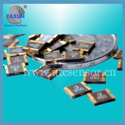
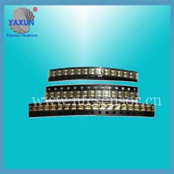
1812 SMD Resettable Fuses Voltage Selection
- PRODUCT DETAIL
Restore fuse selection
1. Determine the following parameters of the circuit:
a Maximum working environment temperature
b Standard operating current
c Maximum working voltage (Umax)
d Maximum fault current (Imax)
2.Select a self-resetting fuse element that can adapt to the maximum ambient temperature of the circuit and the standard working current
Use the temperature-reduced {ambient temperature (° C) operating current (A)} table and select the temperature that best matches the maximum ambient temperature of the circuit. To look up the value of the circuit's standard operating current.
3. Compare the maximum electrical rating of the selected component with the maximum operating voltage and fault current of the circuit
Use electrical characteristics to verify that the components selected in step 2 will use the circuit's maximum operating voltage and fault current.
Check the device's maximum operating voltage and maximum fault current.
Ensure that Umax and Imax are greater than or equal to the maximum operating voltage and maximum fault current of the circuit.
4. Determine the action time of the resettable fuse
The operating time is the amount of time it takes to switch this element to a high resistance state when a fault current appears on the entire device.
To provide the desired protection, it is important to know the operating time of the resettable fuse element.
If you select a component that moves too fast, abnormal or harmful action may occur.
If the component moves too slowly, the protected component may be damaged before the component switches to a high resistance state.
Use a typical operating time curve at 25 ° C to determine if the operating time of a resettable fuse element is too fast or too slow for the circuit.
If yes, go back to step 2 and reselect spare parts.
5.Verify ambient operating temperature
Reduction rate table of ambient temperature and current value for resettable fuse
Ensure that the minimum and maximum ambient temperatures for the application are within the operating temperature range of the resettable fuse element.
Most resettable fuse components have an operating temperature range of -40 ° C to 85 ° C.
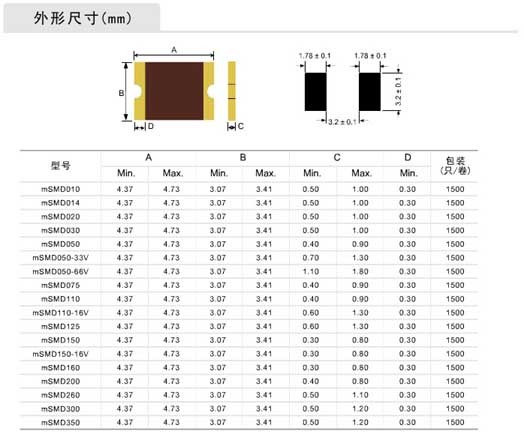
6.Verify the dimensions of the resettable fuse element
Use the form factor chart to compare the form factor of your chosen resettable fuse with the space conditions of your application.
Application fields: all high density circuits
Features: surface mount components, SMD fuse moves faster than normal
Operating current: 0.1A ~ 3.5A
Operating temperature: -40 ℃ to 85 ℃
Lead, halogen-free ecological products, RoHS and REACH standards
Performance specification (25℃)
1. Determine the following parameters of the circuit:
a Maximum working environment temperature
b Standard operating current
c Maximum working voltage (Umax)
d Maximum fault current (Imax)
2.Select a self-resetting fuse element that can adapt to the maximum ambient temperature of the circuit and the standard working current
Use the temperature-reduced {ambient temperature (° C) operating current (A)} table and select the temperature that best matches the maximum ambient temperature of the circuit. To look up the value of the circuit's standard operating current.
3. Compare the maximum electrical rating of the selected component with the maximum operating voltage and fault current of the circuit
Use electrical characteristics to verify that the components selected in step 2 will use the circuit's maximum operating voltage and fault current.
Check the device's maximum operating voltage and maximum fault current.
Ensure that Umax and Imax are greater than or equal to the maximum operating voltage and maximum fault current of the circuit.
4. Determine the action time of the resettable fuse
The operating time is the amount of time it takes to switch this element to a high resistance state when a fault current appears on the entire device.
To provide the desired protection, it is important to know the operating time of the resettable fuse element.
If you select a component that moves too fast, abnormal or harmful action may occur.
If the component moves too slowly, the protected component may be damaged before the component switches to a high resistance state.
Use a typical operating time curve at 25 ° C to determine if the operating time of a resettable fuse element is too fast or too slow for the circuit.
If yes, go back to step 2 and reselect spare parts.
5.Verify ambient operating temperature
Reduction rate table of ambient temperature and current value for resettable fuse
Ensure that the minimum and maximum ambient temperatures for the application are within the operating temperature range of the resettable fuse element.
Most resettable fuse components have an operating temperature range of -40 ° C to 85 ° C.
6.Verify the dimensions of the resettable fuse element
Use the form factor chart to compare the form factor of your chosen resettable fuse with the space conditions of your application.
Application fields: all high density circuits
Features: surface mount components, SMD fuse moves faster than normal
Operating current: 0.1A ~ 3.5A
Operating temperature: -40 ℃ to 85 ℃
Lead, halogen-free ecological products, RoHS and REACH standards
Performance specification (25℃)
| Model | Vmax | Imax | Ih | It | Pd | Time to trip | Resistance | ||
| V | A | A | A | W | Current(A) | Time(s) | Rmin(Ω) | R1max(Ω) | |
| SMD1812P010TF | 30.0 | 10 | 0.10 | 0.30 | 0.8 | 0.5 | 1.50 | 2.000 | 15.000 |
| SMD1812P014TF | 60.0 | 10 | 0.14 | 0.34 | 0.8 | 1.5 | 0.15 | 1.000 | 6.000 |
| SMD1812P020TF | 30.0 | 40 | 0.20 | 0.40 | 0.8 | 8.0 | 0.02 | 0.800 | 5.000 |
| SMD1812P030TF | 30.0 | 40 | 0.30 | 0.60 | 0.8 | 8.0 | 0.10 | 0.400 | 3.500 |
| SMD1812P050TF | 16.0 | 40 | 0.50 | 1.00 | 0.8 | 8.0 | 0.15 | 0.150 | 1.200 |
| SMD1812P050TF/24V | 24.0 | 40 | 0.50 | 1.00 | 0.8 | 8.0 | 0.15 | 0.150 | 1.200 |
| SMD1812P075TF | 16.0 | 40 | 0.75 | 1.50 | 1.0 | 8.0 | 0.20 | 0.100 | 0.500 |
| SMD1812P110TF | 8.0 | 40 | 1.10 | 2.20 | 1.0 | 8.0 | 0.30 | 0.060 | 0.260 |
| SMD1812P110TF/16V | 16.0 | 40 | 1.10 | 2.20 | 1.0 | 8.0 | 0.30 | 0.070 | 0.270 |
| SMD1812P125TF | 8.0 | 40 | 1.25 | 2.50 | 0.8 | 8.0 | 0.40 | 0.050 | 0.220 |
| SMD1812P150TF | 8.0 | 40 | 1.50 | 3.00 | 1.0 | 8.0 | 0.50 | 0.040 | 0.170 |
| SMD1812P160TF | 8.0 | 40 | 1.60 | 3.20 | 1.0 | 8.0 | 1.00 | 0.040 | 0.160 |
| SMD1812P200TF | 8.0 | 40 | 2.00 | 4.00 | 1.0 | 8.0 | 2.00 | 0.030 | 0.110 |
| SMD1812P260TF | 8.0 | 40 | 2.60 | 5.00 | 1.2 | 8.0 | 2.50 | 0.015 | 0.060 |
| SMD1812P300TF | 6.0 | 40 | 3.00 | 5.00 | 1.2 | 8.0 | 4.00 | 0.010 | 0.050 |
| Sign | Definition |
| Ih | Hold current-maximum current at which the device will not trip at 25℃ |
| It | Trip current-minimum current at which the device will always trip at 25℃ |
| Vmax | Maximum voltage at which the device will not trip |
| Vmaxi | Maximum voltage device can withstand without damage at it rated current |
| Imax | Maximum fault current device can withstand without damage at rated voltage |
| Rmin | Minimum device resistance at 25℃ prior to tripping |
| Rmax | Maximum device resistance at 25℃ prior to tripping |
| Figure | The Figure of PTC |
| Lead | Lead diameter |