Protection scheme of PTC fuse of mobile phone battery
Protection circuit for mobile phone battery. The cell of the mobile phone battery is actually relatively fragile, so complete protection measures are essential for a qualified mobile phone battery. Here is the text:
The resistance value of cold PTC is only tens of milliohms, while the resistance value of hot state can reach hundreds of kiloohms.
3. Current protection circuit of lithium ion battery
For a detailed description of the principle of the lithium-ion battery protection circuit, please refer to
This article mainly illustrates with legends
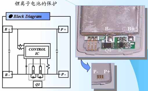
The left is a schematic diagram of a typical lithium-ion protection circuit: B+, and B- represent typical positive and negative electrodes, while P+ and P- represent the positive and negative output of the finished mobile phone battery (see the right).
4. Protection parameters of lithium-ion protection circuit
In addition, complex and advanced lithium-ion batteries (such as smart lithium-ion batteries) will also contain identification codes for temperature protection, fuel gauge, real-time clock and electronic range.
5. Detailed explanation of the protection principle of lithium-ion battery
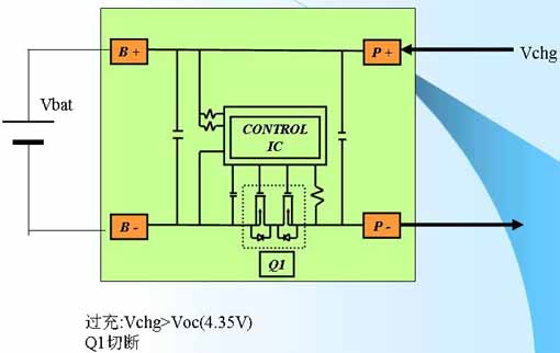
1. Overcharge protection
When the charging voltage exceeds the protection value, the protection circuit is triggered to turn off the switch Q1.
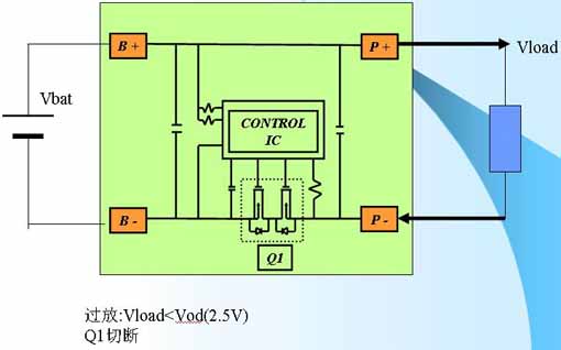
2. Over discharge protection
When the load causes the battery voltage to drop below the protection voltage, the protection circuit is triggered and Q1 is turned off.
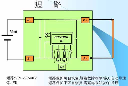
3. Short circuit protection
There are two types of short-circuit protection circuits. One is that once triggered, the short-circuit fault is eliminated and Q1 turns on by itself. The other type will not recover by itself after being triggered, and Q1 will not be released until the outside is forced to charge. These two types of protection circuits coexist on the market.
Integrated circuit
A typical lithium-ion battery integrated protection circuit, from left to right are fuel gauge circuit/protection circuit/real-time clock.
One advantage of the real-time clock circuit in the battery pack is that even if the battery is unplugged from the mobile phone, the clock will not be lost, as long as the battery voltage does not drop below 3.0V. But now most real-time clock circuits are placed in mobile phones and only rely on a small-capacity backup battery for power supply. After the phone down, maintain a very limited time.
1. Current protection of Ni-MH battery
The protective device of the Ni-MH battery of the mobile phone is very simple, which is the same thing as the flat belt that straddles the two battery cells in the picture. It is called a recoverable fuse, or PTC, which is the English abbreviation for positive temperature coefficient thermistor. On the circuit, it is connected in series in the power supply loop. Once a large current (such as a short circuit) occurs, it will quickly increase its own resistance value due to its PTC effect, which will act as a circuit breaker.2. Introduction of PTC
PTC positive temperature coefficient thermistor is also called polymer resettable fuse. The polymer resettable fuse consists of a polymer matrix and carbon black particles that make it conductive. Since the polymer resettable fuse is a conductor, current will flow through it. When an overcurrent flows through the polymer resettable fuse, the heat generated (I 2 R) will cause it to expand. As a result, the carbon black particles will separate and the resistance of the polymer resettable fuse will increase. This will cause the polymer resettable fuse to generate heat faster, expand more, and further increase the resistance. When the temperature reaches 125 °C, the resistance changes significantly, resulting in a significant reduction in current. At this time, the small current flowing through the polymer resettable fuse is enough to keep it at this temperature and in a high resistance state. When the fault is cleared, the polymer resettable fuse shrinks to its original shape to reconnect the carbon black particles, thereby reducing the resistance to the level of the specified holding current. The above process can be cycled many times. The legend illustrates the protection principle of PTC as shown in the figure below:The resistance value of cold PTC is only tens of milliohms, while the resistance value of hot state can reach hundreds of kiloohms.
3. Current protection circuit of lithium ion battery
For a detailed description of the principle of the lithium-ion battery protection circuit, please refer to
This article mainly illustrates with legends
The left is a schematic diagram of a typical lithium-ion protection circuit: B+, and B- represent typical positive and negative electrodes, while P+ and P- represent the positive and negative output of the finished mobile phone battery (see the right).
4. Protection parameters of lithium-ion protection circuit
In addition, complex and advanced lithium-ion batteries (such as smart lithium-ion batteries) will also contain identification codes for temperature protection, fuel gauge, real-time clock and electronic range.
5. Detailed explanation of the protection principle of lithium-ion battery
1. Overcharge protection
When the charging voltage exceeds the protection value, the protection circuit is triggered to turn off the switch Q1.
2. Over discharge protection
When the load causes the battery voltage to drop below the protection voltage, the protection circuit is triggered and Q1 is turned off.
3. Short circuit protection
There are two types of short-circuit protection circuits. One is that once triggered, the short-circuit fault is eliminated and Q1 turns on by itself. The other type will not recover by itself after being triggered, and Q1 will not be released until the outside is forced to charge. These two types of protection circuits coexist on the market.
Integrated circuit
A typical lithium-ion battery integrated protection circuit, from left to right are fuel gauge circuit/protection circuit/real-time clock.
One advantage of the real-time clock circuit in the battery pack is that even if the battery is unplugged from the mobile phone, the clock will not be lost, as long as the battery voltage does not drop below 3.0V. But now most real-time clock circuits are placed in mobile phones and only rely on a small-capacity backup battery for power supply. After the phone down, maintain a very limited time.


