NTC thermistor used in refrigerator thermostat temperature sensing
The electronic temperature controller not only has the same temperature characteristics as the pressure type thermostat, but also can easily change the temperature characteristics according to the requirements of the refrigerator manufacturer. The process of changing the temperature characteristics of the pressure thermostat is eliminated, and the process of producing new parts needs to be organized. Speed up the process of matching new products and reduce production costs. The electronic thermostat also has a semi-automatic defrost function. The defrost heater can be manually activated as needed, and the defrost is automatically stopped when the set temperature is reached.
working principle
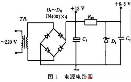
1.1 Power supply
As shown in Figure 1. The AC 220V is stepped down by the transformer TR1, and then rectified and filtered to output about 12V DC voltage, which is supplied to the compressor relay RC and the defrosting heater relay RH. At the same time, after R20, D8, C7 voltage regulation, the output of about 6.8V DC voltage is supplied to the remaining logic control circuits.
 1.2 Temperature control
The electronic temperature controller uses a negative temperature coefficient (NTC) thermistor Rt1, Rt2 as a temperature sensing element. Its resistance value is about 3k8 at normal temperature (25 °C), the normal working temperature range is between -60 and +100 °C, and it is packaged with epoxy resin and metal casing to appropriately reduce the temperature sensing sensitivity. It has high sensitivity, small thermal inertia and high resistance at low temperature. The resistance value is basically linear and the price is cheap in a certain temperature range, and can be widely used for temperature control and detection.
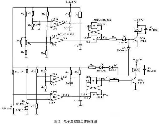
The electronic thermostat logic control principle is shown in Figure 2. The opening and closing of the refrigerator compressor is controlled by the temperature of the refrigerating compartment, and Rt1 (refrigerating chamber thermistor) is the refrigerating compartment temperature sensor. Rt1 and R19 form a voltage divider, as the temperature of the refrigerating compartment changes. The 5,6-pin voltage V(6) of IC1 (four-voltage comparator LM339) changes accordingly. The voltage of pin 4 of IC1 is constant.
V(4)=30/(30+20)&TImes; 6.8=4.1V
The voltage at pin 7 of IC1 is determined by the temperature adjustment potentiometer R4. When the potentiometer R4 is adjusted to the low gear (thermostat thermostat), the equivalent resistance of R3, R4 is R34=0.49k8. at this time,
V(7)=(1.1+0.49)/(1.1+0.49+2.4)&TImes;6.8=2.71V
When the potentiometer R4 is adjusted to the high level (the temperature controller is cold), at this time,
V'(7)=1.1/(1.1+0.52+2.4)&TImes;6.8=1.86V
When the potentiometer R4 is adjusted to the middle position (the midpoint of the thermostat), the resistance of the R4 potentiometer is selected to vary linearly. At this point, V"(7)=2.3V can be calculated.
It can be seen from the voltage change value of pin 7 of IC1: V′′(7)=0.5(V(7)+V′(7))
Thus, by properly selecting the thermistor Rt1, the temperature of the thermostat shutdown can vary substantially linearly with the position of the potentiometer. When the refrigerator is energized, the resistance of Rt1 is small due to the higher temperature. At this time, V(6)>V(7), V(6)>V(4)
Therefore, IC1 outputs V(1) = "0" and V(2) = "1".
At this time, the 4 pin output of IC2 (four or non-gate circuit CD4001) V02 = "1", the compressor relay RC is sucked, and the refrigerator starts to cool. As the temperature decreases, the resistance of Rt1 increases and V(6) decreases. When the temperature drops to about 4 ° C,
Rt1=6.7k8, at this time V(6)=4.1V
Since V(4)=4.1V is unchanged, V(6)V(7)
At this time, V(1)=“0”, V(2)=“0”.
Therefore, the output of IC2 V02 = "1" remains unchanged, and the refrigerator continues to cool.
As the temperature is further reduced, the resistance of Rt1 continues to increase. Assuming that the thermostat potentiometer is placed at the midpoint, when the temperature is lowered to about -20 ° C, Rt1 = 19.6 k8, at which time V (6) = 2.3 V.
Therefore V(6)
The output of IC1 is V(1) = "1" and V(2) = "0".
At this time, the output of IC2 V02 = "0", the compressor relay RC is released, and the refrigerator stops cooling.
After stopping the cooling, the temperature in the refrigerator rises, the resistance of Rt1 decreases, and V(6) increases. At this time, V(6)>V(7)=2.3V (midpoint position), but V(6)
Therefore, the output of IC2 V02 = "0", remains unchanged, and the compressor does not work. As the temperature increases further, when it reaches about +4 ° C, Rt1 = 6.7k8, V (6) = 4.1V.
Therefore, when V(6)>V(7), V(6)>V(4), IC1 outputs V(1)=“0” and V(2)=“1”. The IC2 output V02 is again inverted to a high voltage, the compressor relay RC is pulled in, and the refrigerator is re-cooled. Repeatedly, the temperature at the refrigerating chamber probe is controlled to fluctuate between +4 and -20 °C.
Normally, when the buttons AN101 and AN102 are not pressed: the voltage of 8 pins of IC1 V(8)=V(11)=5.65.6+3&TImes;6.8=4.43V.
IC1's 10-pin voltage V(10)=6.8V.
IC9's 9-pin voltage V(9) changes with the resistance value of the defrosting thermistor Rt2, the temperature rises, the resistance of Rt2 decreases, and V(9) increases; the temperature decreases, and V(9) decreases.
When the freezer compartment temperature is high, then V(9) > V(8). At this time, even if the defrosting button AN101 is pressed, since the output terminal V(14) of IC1 = "1", the output V(01)' of IC2 = "0". The defrosting relay RH is not conducting, so the defrosting heating is not performed at this time.
When the freezer compartment temperature is low, let V(9)V(11), then the output terminal V(13) of IC1 = "0", then the output terminal V01' of the IC2 = "0" remains unchanged. Defrost heating will not be performed.
At this time, if the AN101 button is pressed, V(10)=0
If the defrost stop button AN102 is pressed during the defrost heating process, then V(8)=V(11)=0.7V
After releasing the button AN102, the IC2 output V01'=“0” remains unchanged, and the cooling state is maintained.
It can be seen from the above analysis that the electronic thermostat realizes the semi-automatic defrost function.
It can be seen from the above analysis that the electronic temperature controller's starting temperature C/ON (W/ON)=4°C remains unchanged, the shutdown temperature varies between -16 and -24 °C, and the defrost reset temperature is about 6.5 °C. It achieves the temperature-reset temperature characteristic requirements and has a semi-automatic defrost function. The utility model has the advantages of high temperature control precision, easy organization and quick design, and the change of the corresponding resistance combination can easily change the startup, shutdown and defrosting temperature characteristics. The electronic thermostat has been trial-produced in batches and tested by relevant manufacturers, and the market has responded well.
working principle
1.1 Power supply
As shown in Figure 1. The AC 220V is stepped down by the transformer TR1, and then rectified and filtered to output about 12V DC voltage, which is supplied to the compressor relay RC and the defrosting heater relay RH. At the same time, after R20, D8, C7 voltage regulation, the output of about 6.8V DC voltage is supplied to the remaining logic control circuits.
The electronic temperature controller uses a negative temperature coefficient (NTC) thermistor Rt1, Rt2 as a temperature sensing element. Its resistance value is about 3k8 at normal temperature (25 °C), the normal working temperature range is between -60 and +100 °C, and it is packaged with epoxy resin and metal casing to appropriately reduce the temperature sensing sensitivity. It has high sensitivity, small thermal inertia and high resistance at low temperature. The resistance value is basically linear and the price is cheap in a certain temperature range, and can be widely used for temperature control and detection.
The electronic thermostat logic control principle is shown in Figure 2. The opening and closing of the refrigerator compressor is controlled by the temperature of the refrigerating compartment, and Rt1 (refrigerating chamber thermistor) is the refrigerating compartment temperature sensor. Rt1 and R19 form a voltage divider, as the temperature of the refrigerating compartment changes. The 5,6-pin voltage V(6) of IC1 (four-voltage comparator LM339) changes accordingly. The voltage of pin 4 of IC1 is constant.
V(4)=30/(30+20)&TImes; 6.8=4.1V
The voltage at pin 7 of IC1 is determined by the temperature adjustment potentiometer R4. When the potentiometer R4 is adjusted to the low gear (thermostat thermostat), the equivalent resistance of R3, R4 is R34=0.49k8. at this time,
V(7)=(1.1+0.49)/(1.1+0.49+2.4)&TImes;6.8=2.71V
When the potentiometer R4 is adjusted to the high level (the temperature controller is cold), at this time,
V'(7)=1.1/(1.1+0.52+2.4)&TImes;6.8=1.86V
When the potentiometer R4 is adjusted to the middle position (the midpoint of the thermostat), the resistance of the R4 potentiometer is selected to vary linearly. At this point, V"(7)=2.3V can be calculated.
It can be seen from the voltage change value of pin 7 of IC1: V′′(7)=0.5(V(7)+V′(7))
Thus, by properly selecting the thermistor Rt1, the temperature of the thermostat shutdown can vary substantially linearly with the position of the potentiometer. When the refrigerator is energized, the resistance of Rt1 is small due to the higher temperature. At this time, V(6)>V(7), V(6)>V(4)
Therefore, IC1 outputs V(1) = "0" and V(2) = "1".
At this time, the 4 pin output of IC2 (four or non-gate circuit CD4001) V02 = "1", the compressor relay RC is sucked, and the refrigerator starts to cool. As the temperature decreases, the resistance of Rt1 increases and V(6) decreases. When the temperature drops to about 4 ° C,
Rt1=6.7k8, at this time V(6)=4.1V
Since V(4)=4.1V is unchanged, V(6)V(7)
At this time, V(1)=“0”, V(2)=“0”.
Therefore, the output of IC2 V02 = "1" remains unchanged, and the refrigerator continues to cool.
As the temperature is further reduced, the resistance of Rt1 continues to increase. Assuming that the thermostat potentiometer is placed at the midpoint, when the temperature is lowered to about -20 ° C, Rt1 = 19.6 k8, at which time V (6) = 2.3 V.
Therefore V(6)
The output of IC1 is V(1) = "1" and V(2) = "0".
At this time, the output of IC2 V02 = "0", the compressor relay RC is released, and the refrigerator stops cooling.
After stopping the cooling, the temperature in the refrigerator rises, the resistance of Rt1 decreases, and V(6) increases. At this time, V(6)>V(7)=2.3V (midpoint position), but V(6)
Therefore, the output of IC2 V02 = "0", remains unchanged, and the compressor does not work. As the temperature increases further, when it reaches about +4 ° C, Rt1 = 6.7k8, V (6) = 4.1V.
Therefore, when V(6)>V(7), V(6)>V(4), IC1 outputs V(1)=“0” and V(2)=“1”. The IC2 output V02 is again inverted to a high voltage, the compressor relay RC is pulled in, and the refrigerator is re-cooled. Repeatedly, the temperature at the refrigerating chamber probe is controlled to fluctuate between +4 and -20 °C.
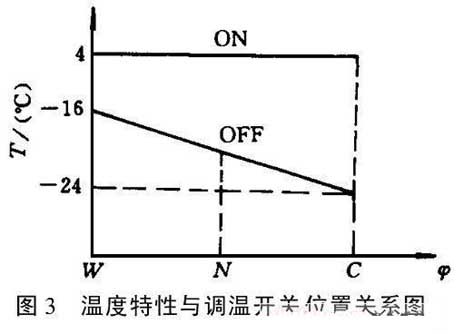
It can be seen from the above analysis that the temperature control temperature (C/ON, W/ON) of the thermostat remains unchanged at +4 °C. The shutdown temperature can be changed with the position of the thermostat potentiometer. The relationship between the temperature characteristics and the position of the thermostat potentiometer is shown in Fig. 3. In this case:
C/OFF=-24°C, W/OFF=-16°C
N/OFF=-20°C, C/ON=W/ON=+4°C
Thereby achieving the requirements of the WDF series thermostat constant temperature reset. By changing the resistance parameters, the temperature characteristics of the opening and stopping can be changed to meet the requirements of different users.
1.3 Semi-automatic defrost
The semi-automatic defrost control circuit consists of the other half of IC1 (four voltage comparator LM339) and its peripheral circuits. Analysis of IC1:
Normally, when the buttons AN101 and AN102 are not pressed: the voltage of 8 pins of IC1 V(8)=V(11)=5.65.6+3&TImes;6.8=4.43V.
IC1's 10-pin voltage V(10)=6.8V.
IC9's 9-pin voltage V(9) changes with the resistance value of the defrosting thermistor Rt2, the temperature rises, the resistance of Rt2 decreases, and V(9) increases; the temperature decreases, and V(9) decreases.
When the freezer compartment temperature is high, then V(9) > V(8). At this time, even if the defrosting button AN101 is pressed, since the output terminal V(14) of IC1 = "1", the output V(01)' of IC2 = "0". The defrosting relay RH is not conducting, so the defrosting heating is not performed at this time.
When the freezer compartment temperature is low, let V(9)V(11), then the output terminal V(13) of IC1 = "0", then the output terminal V01' of the IC2 = "0" remains unchanged. Defrost heating will not be performed.
At this time, if the AN101 button is pressed, V(10)=0
If the defrost stop button AN102 is pressed during the defrost heating process, then V(8)=V(11)=0.7V
After releasing the button AN102, the IC2 output V01'=“0” remains unchanged, and the cooling state is maintained.
It can be seen from the above analysis that the electronic thermostat realizes the semi-automatic defrost function.
It can be seen from the above analysis that the electronic temperature controller's starting temperature C/ON (W/ON)=4°C remains unchanged, the shutdown temperature varies between -16 and -24 °C, and the defrost reset temperature is about 6.5 °C. It achieves the temperature-reset temperature characteristic requirements and has a semi-automatic defrost function. The utility model has the advantages of high temperature control precision, easy organization and quick design, and the change of the corresponding resistance combination can easily change the startup, shutdown and defrosting temperature characteristics. The electronic thermostat has been trial-produced in batches and tested by relevant manufacturers, and the market has responded well.


