Measuring a variety of temperature sensors and digital output applications
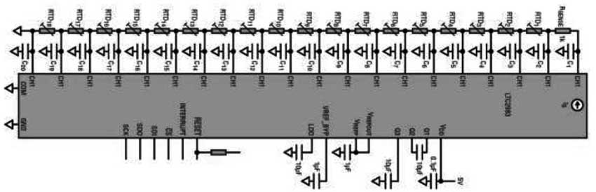
Multi-sensor high accuracy digital temperature measurement system LTC2983, which can measure a variety of temperature sensors and digitally output the results (in oC or oF) with 0.1oC accuracy and 0.001oC resolution. Today we are talking about why the LTC2983 can measure 18 two-wire RTDs? A single LTC2983 temperature measurement device can support up to 18 two-wire RTD probes (as shown in Figure 1). Each RTD measurement involves simultaneously detecting two voltages generated across RSENSE and RTD probe RTDx due to current IS. Differential detection is performed for each voltage, and given the high common-mode rejection ratio of the LTC2983, the number of RTDs in the stack does not adversely affect individual measurements.
Once the RTD is selected, the appropriate IS and RSENSE should be selected so that the voltage at the top of the resistor stack (V at the CH1 input) does not exceed the input common-mode limit of the LTC2983 over the full operating temperature range of the system. The requirement is expressed as:
Consider the system shown in Figure 1 and assume the following restrictions: The 5V power rail, all RTD probes are PT-100 and the maximum expected temperature is measured at 150 °C. Table 1 lists the channel assignment words for each PT-100 probe. Among them, in this example, CH3 detects the RTD1 probe, and CH4 detects the RTD2 probe. The resistors connected to CH2 are configured as shown in Table 2.
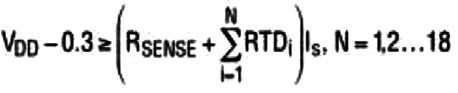
Once the excitation current source is enabled, the R and C links take a limited amount of time to stabilize. This is the settling time tS. tS depends on the number and value of individual resistors (RSENSE and RTD) and capacitors on each input node. The upper limit of tS can be estimated by the aggregate of the total RC, but doing so will result in too pessimistic results. Another way to get tS is to simply simulate a circuit, as shown in Figure 2.
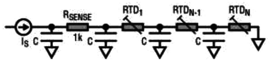
Figure 2 Delay line model of the RTD stack
The results of the simulation are shown in Figure 3. Here, all capacitors are chosen to be 100 nF and RSENSE is 1 kΩ. Each line represents the settling time tS required to settle to within 0.1% of the final value of the voltage across the last RTD in the stack. For each graph, all RTDs are of the same type.
image 3 Simulation settling time of the RTD stack
By default, the LTC2983 inserts a delay time tDELAY = 1 ms between the enable of the excitation current source and the start of the ADC conversion. However, when there are more than 2 PT-100 probes in the RTD stack, this delay time is not enough (see Figure 3).
tDELAY can be incremented by setting the value in the MUX Configuration Register 0x0FF. This register is cleared by default. Each additional LSB of register value represents a default tDELAY of 100μs. For example, writing 0x10 to the 0x0FF register produces the result:

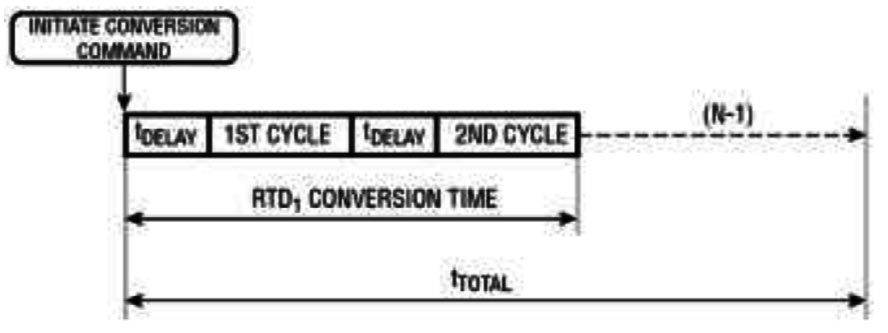
Figure 4 Total conversion time of the RTD stack
tDELAY is inserted before each individual ADC cycle. Each RTD measurement includes two ADC cycles. Thus, the total conversion time of the RTD stack is approximately:
The t DELAY in the formula can be set by the user.
tCONV is given in the “CompleteSystemElectricalCharacteristics” table in the product manual, which is typically 164 ms (including the default MUX delay) and N is the number of RTDs to be measured. tTOTAL is shown in Figure 4.
in conclusion
The LTC2983 can be connected to up to 18 two-wire RTD probes, but the stability delay caused by the RC system must be taken into account. This problem may be exacerbated by the number and type of RTD probes used. The delay problem can be investigated using the model and simulation presented in this paper.
Figure 1 LTC2983 can support 18 RTD sensors
The choice of RTD probe depends on system accuracy and sensitivity requirements. For example, assuming a two-wire probe is used, it can be shown that the PT-1000 is more robust in the presence of wiring parasitic resistance.Once the RTD is selected, the appropriate IS and RSENSE should be selected so that the voltage at the top of the resistor stack (V at the CH1 input) does not exceed the input common-mode limit of the LTC2983 over the full operating temperature range of the system. The requirement is expressed as:
Consider the system shown in Figure 1 and assume the following restrictions: The 5V power rail, all RTD probes are PT-100 and the maximum expected temperature is measured at 150 °C. Table 1 lists the channel assignment words for each PT-100 probe. Among them, in this example, CH3 detects the RTD1 probe, and CH4 detects the RTD2 probe. The resistors connected to CH2 are configured as shown in Table 2.
Table 1. CH2 to CH20RTD Channel Assignment Words
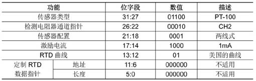
Table 2. Detect resistor channel configuration word
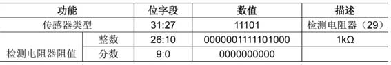
RTD stack settling timeTable 2. Detect resistor channel configuration word
Once the excitation current source is enabled, the R and C links take a limited amount of time to stabilize. This is the settling time tS. tS depends on the number and value of individual resistors (RSENSE and RTD) and capacitors on each input node. The upper limit of tS can be estimated by the aggregate of the total RC, but doing so will result in too pessimistic results. Another way to get tS is to simply simulate a circuit, as shown in Figure 2.
Figure 2 Delay line model of the RTD stack
The results of the simulation are shown in Figure 3. Here, all capacitors are chosen to be 100 nF and RSENSE is 1 kΩ. Each line represents the settling time tS required to settle to within 0.1% of the final value of the voltage across the last RTD in the stack. For each graph, all RTDs are of the same type.
image 3 Simulation settling time of the RTD stack
By default, the LTC2983 inserts a delay time tDELAY = 1 ms between the enable of the excitation current source and the start of the ADC conversion. However, when there are more than 2 PT-100 probes in the RTD stack, this delay time is not enough (see Figure 3).
tDELAY can be incremented by setting the value in the MUX Configuration Register 0x0FF. This register is cleared by default. Each additional LSB of register value represents a default tDELAY of 100μs. For example, writing 0x10 to the 0x0FF register produces the result:
It should be noted that the maximum programmable delay is 26.5 ms, which is sufficient for the stability of up to 6 PT-1000 devices (assuming C = 100 nF). As shown in Figure 3 and Figure 4.
Figure 4 Total conversion time of the RTD stack
tDELAY is inserted before each individual ADC cycle. Each RTD measurement includes two ADC cycles. Thus, the total conversion time of the RTD stack is approximately:
The t DELAY in the formula can be set by the user.
tCONV is given in the “CompleteSystemElectricalCharacteristics” table in the product manual, which is typically 164 ms (including the default MUX delay) and N is the number of RTDs to be measured. tTOTAL is shown in Figure 4.
in conclusion
The LTC2983 can be connected to up to 18 two-wire RTD probes, but the stability delay caused by the RC system must be taken into account. This problem may be exacerbated by the number and type of RTD probes used. The delay problem can be investigated using the model and simulation presented in this paper.


