Multi-channel PT100-III type signal conversion module
Abstract: This paper presents the hardware and software design of multi-channel PT100-III signal conversion module.
Key words: three-wire system; PT100; MODBUS
introduction
PT100 is a widely used temperature measuring element. It has unparalleled advantages in any temperature sensor ranging from -50 °C to 600 °C, including high precision, good stability and strong anti-interference ability. Since the resistance value of platinum thermal resistance is nonlinear with temperature, this module needs to perform nonlinear correction. The general module is corrected by analog circuit. The accuracy of this correction is not high, and the degree of disturbance such as temperature drift is also large. This module uses software look-up table interpolation method to correct, and finally converts to type III signal. The type III signal is the change of the 4-20 mA current on the output line when the measured signal changes from the down range to the upper range (0% to 100%). In addition, the module also has a communication port of MODBUS protocol, which can be directly connected to any MODBUS port.
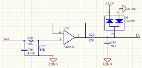
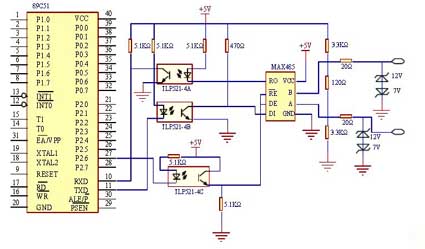
Figure 2 host circuit
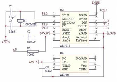
Figure 3 D / A circuit
system design
The whole module is based on AVR's new Atmega16 microcontroller, which uses a three-wire system to remove the inaccuracy of the zero point caused by the wire resistance. The differential amplifier circuit directly obtains the signal voltage of 0~5V, so that it can be directly input to the A/D converter.
In the data processing section, the resistance value of every 10 ° C in the PT100 index table is written into the flash memory. In this way, the voltage value will be returned to the resistance value, so that the table is checked. When the resistance is between a certain segment, linear processing is performed, so that the degree of linearization of the system can be as high as 0.2%.
The D/A conversion system uses a 373 chip as a latch and uses a weight resistor network for D/A conversion, which saves cost and ensures accuracy. Finally, through a voltage and current conversion part, the signal is transmitted as a type III signal to complete the function of the module.
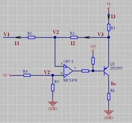
Figure 4 V / I conversion circuit
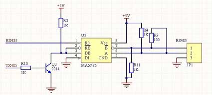
Figure 5 485 communication circuit
Sampling circuit
The sampling circuit is shown in Figure 1. The PT100 is connected to J0 in a three-wire system. In this way, the lengths of the wires connecting the two sides of the PT100 are equal, and are respectively added to the bridge arms on both sides. In this way, the wire resistance is eliminated. When the PT100 outputs 100Ω, the resistance of R1 can be adjusted to adjust the lower temperature limit. When the temperature range is 0~300°C, the voltage of Anolog0 is exactly 0~5V after the bridge voltage is amplified, so that the conversion accuracy of the A/D converter of the single chip microcomputer can be completely used.
Host circuit
The host circuit is shown in Figure 2. The CPU uses Atmega16, which comes with 8 10-bit A/D converters. It has fast conversion speed and high precision, and it does not need to expand any device. The 74LS138 is used to decode and strobe the latches of each channel. With an 8MHz crystal, the speed can fully meet the requirements of the system. The reference voltage for A/D conversion is directly VCC, which saves hardware and simplifies the circuit. Precision regulator devices such as the TL431 can be selected for high accuracy requirements.
D/A conversion circuit
In order to save costs, the system does not use a dedicated D / A conversion chip, but the principle of D / A conversion. Using the weight resistor network for the D/A converter, the accuracy can be guaranteed, and the speed is faster, and the CPU control is relatively simple. The circuit is shown in Figure 3. 74lS373 latch, latching the CPU every time the data is updated. The OE pin is connected to the chip select signal of the 138 chip, and the data is latched on the falling edge of LE.
V/I conversion circuit
The V/I conversion circuit is shown in Figure 4. It converts the voltage signal obtained after A/D conversion into a 4-20 mA type III signal output. I=V/R3.
RS-485 communication circuit
Communication chip uses MAX485 chip, which connects receiving permission with sending permission (see Fig. 5). Use a port line to control, under normal circumstances, accept permission, when you need to send, set to allow.
software design
Software design is the key to this system and it is also a different place. The general platinum resistance to type III signal modules are all analog circuits, and there is no software part. The system uses digital linear correction to greatly improve the accuracy of the module. The software flow is shown in Figure 6. The software is divided into main program, interrupt service subroutine, and all programs are written in C language. The program is debugged at ICCAVR6.30.
Conclusion
The PT100-III type signal conversion module based on single chip microcomputer has the advantages of high precision, digital communication and upgradeability. This module has been used for the detection of flue gas temperature in several thermal power plants. Among them, the type III signal and digital communication are used, and all have achieved good results.
Key words: three-wire system; PT100; MODBUS
introduction
PT100 is a widely used temperature measuring element. It has unparalleled advantages in any temperature sensor ranging from -50 °C to 600 °C, including high precision, good stability and strong anti-interference ability. Since the resistance value of platinum thermal resistance is nonlinear with temperature, this module needs to perform nonlinear correction. The general module is corrected by analog circuit. The accuracy of this correction is not high, and the degree of disturbance such as temperature drift is also large. This module uses software look-up table interpolation method to correct, and finally converts to type III signal. The type III signal is the change of the 4-20 mA current on the output line when the measured signal changes from the down range to the upper range (0% to 100%). In addition, the module also has a communication port of MODBUS protocol, which can be directly connected to any MODBUS port.
Figure 1 sampling circuit
Figure 2 host circuit
Figure 3 D / A circuit
system design
The whole module is based on AVR's new Atmega16 microcontroller, which uses a three-wire system to remove the inaccuracy of the zero point caused by the wire resistance. The differential amplifier circuit directly obtains the signal voltage of 0~5V, so that it can be directly input to the A/D converter.
In the data processing section, the resistance value of every 10 ° C in the PT100 index table is written into the flash memory. In this way, the voltage value will be returned to the resistance value, so that the table is checked. When the resistance is between a certain segment, linear processing is performed, so that the degree of linearization of the system can be as high as 0.2%.
The D/A conversion system uses a 373 chip as a latch and uses a weight resistor network for D/A conversion, which saves cost and ensures accuracy. Finally, through a voltage and current conversion part, the signal is transmitted as a type III signal to complete the function of the module.
Figure 4 V / I conversion circuit
Figure 5 485 communication circuit
The sampling circuit is shown in Figure 1. The PT100 is connected to J0 in a three-wire system. In this way, the lengths of the wires connecting the two sides of the PT100 are equal, and are respectively added to the bridge arms on both sides. In this way, the wire resistance is eliminated. When the PT100 outputs 100Ω, the resistance of R1 can be adjusted to adjust the lower temperature limit. When the temperature range is 0~300°C, the voltage of Anolog0 is exactly 0~5V after the bridge voltage is amplified, so that the conversion accuracy of the A/D converter of the single chip microcomputer can be completely used.
Host circuit
The host circuit is shown in Figure 2. The CPU uses Atmega16, which comes with 8 10-bit A/D converters. It has fast conversion speed and high precision, and it does not need to expand any device. The 74LS138 is used to decode and strobe the latches of each channel. With an 8MHz crystal, the speed can fully meet the requirements of the system. The reference voltage for A/D conversion is directly VCC, which saves hardware and simplifies the circuit. Precision regulator devices such as the TL431 can be selected for high accuracy requirements.
D/A conversion circuit
In order to save costs, the system does not use a dedicated D / A conversion chip, but the principle of D / A conversion. Using the weight resistor network for the D/A converter, the accuracy can be guaranteed, and the speed is faster, and the CPU control is relatively simple. The circuit is shown in Figure 3. 74lS373 latch, latching the CPU every time the data is updated. The OE pin is connected to the chip select signal of the 138 chip, and the data is latched on the falling edge of LE.
V/I conversion circuit
The V/I conversion circuit is shown in Figure 4. It converts the voltage signal obtained after A/D conversion into a 4-20 mA type III signal output. I=V/R3.
RS-485 communication circuit
Communication chip uses MAX485 chip, which connects receiving permission with sending permission (see Fig. 5). Use a port line to control, under normal circumstances, accept permission, when you need to send, set to allow.
software design
Software design is the key to this system and it is also a different place. The general platinum resistance to type III signal modules are all analog circuits, and there is no software part. The system uses digital linear correction to greatly improve the accuracy of the module. The software flow is shown in Figure 6. The software is divided into main program, interrupt service subroutine, and all programs are written in C language. The program is debugged at ICCAVR6.30.
Conclusion
The PT100-III type signal conversion module based on single chip microcomputer has the advantages of high precision, digital communication and upgradeability. This module has been used for the detection of flue gas temperature in several thermal power plants. Among them, the type III signal and digital communication are used, and all have achieved good results.


