Making Thermostat with DS18B20 and Programming
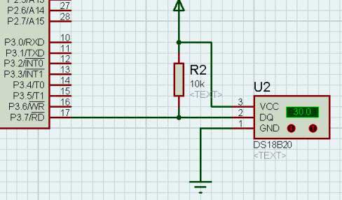
The DS18B20 is a commonly used temperature sensor chip that occupies only one IO port of the microcontroller and is especially convenient to use. It is important to note that because it only uses one IO port to communicate with the MCU, the communication time for reading the temperature value is relatively long and the timing requirements are strict. It is not allowed to be interfered by other interrupts of the microcontroller during communication. Therefore, in the actual project, once the system selects this sensor chip, you should never use the dynamic scanning digital tube display mode. Otherwise, when the interrupt reading temperature is turned off, the display of the digital tube will have a slight "blinking" phenomenon.
The DS18B20 has a temperature range of -55 degrees to 125 degrees. The error is +-0.5 degrees in the temperature range of -10 degrees to 85 degrees, which can meet most common temperature measurement requirements.
(1) Hardware platform
Based on Zhu Zhaoyu 51 single-chip learning board.
(2) to achieve the function
This program has only one window. This window has 2 partial displays.
The first part is the 7, 6, and 5 digits, showing the set temperature.
The second part is the 4th, 3rd, 2nd, and 1st digit tube, showing the actual ambient temperature. The 4th digit tube displays the positive and negative sign bits.
The S1 button is a plus button, and the S5 button is a minus button. With them, you can set the "set temperature" directly.
An LED light is used to simulate an industrially controlled relay.
When the actual temperature is lower than or equal to the set temperature by 2 degrees or less, the LED of the analog relay lights up.
When the actual temperature is equal to or greater than the set temperature, the LED of the analog relay is off.
When the actual temperature is within the set temperature and the set temperature minus 2 degrees, the LED of the analog relay maintains the status quo. This 2 degree range is used to buffer the temperature difference to prevent the relay from frequently switching around the critical temperature.
(3) The source code is explained as follows
#include "REG52.H"
#define const_voice_short 40 //The duration of the buzzer short call
#define const_key_TIme1 20 //Time to debounce delay
#define const_key_TIme2 20 //Time to debounce delay
#define const_ds18b20_sampling_TIme 180 //Accumulate the time of the main loop, the time of each sampling clock chip
Void iniTIal_myself(void);
Void initial_peripheral(void);
Void delay_short(unsigned int uiDelayShort);
Void delay_long(unsigned int uiDelaylong);
/ / Drive the digital tube 74HC595
Void dig_hc595_drive(unsigned char ucDigStatusTemp16_09, unsigned char ucDigStatusTemp08_01);
Void display_drive(void); //Display the driver function of the digital tube font
Void display_service(void); //displayed window menu service program
//Drive the LED 74HC595
Void hc595_drive(unsigned char ucLedStatusTemp16_09, unsigned char ucLedStatusTemp08_01);
Void T0_time(void); //Timed interrupt function
Void key_service(void); //button service application
Void key_scan(void);//key scan function placed in the timer interrupt
Void temper_control_service(void); //temperature control program
Void ds18b20_sampling(void); //ds18b20 sampling program
Void ds18b20_reset(); //Reset the timing of ds18b20
Unsigned char ds_read_byte(void ); //Read one byte
Void ds_write_byte(unsigned char dat); //write a byte
Unsigned int get_temper(); //Read the temperature value without conversion
Sbit dq_dr_sr=P2^6; //ds18b20 data drive line
Sbit key_sr1=P0^0; // corresponding to the S1 key of the Zhu Zhaoyu learning board
Sbit key_sr2=P0^1; // corresponding to the S5 key of Zhu Zhaoyu learning board
Sbit led_dr=P3^5; //LED lights, relays in analog industrial control
Sbit key_gnd_dr=P0^4; // Simulate the ground GND of the independent button, so it must always output low level
Sbit beep_dr=P2^7; //Buzzer drive IO port
Sbit dig_hc595_sh_dr=P2^0; // digital tube 74HC595 program
Sbit dig_hc595_st_dr=P2^1;
Sbit dig_hc595_ds_dr=P2^2;
Sbit hc595_sh_dr=P2^3; //74HC595 program for LED lights
Sbit hc595_st_dr=P2^4;
Sbit hc595_ds_dr=P2^5;
Unsigned int uiSampingCnt=0; // Collect the timer of Ds1302 and update it once every second.
Unsigned char ucSignFlag=0; // positive and negative signs. 0 represents a positive number and 1 represents a negative number, indicating how many degrees below zero.
Unsigned long ulCurrentTemper=33; // actual temperature
Unsigned long ulSetTemper=26; //Set the temperature
Unsigned int uiTemperTemp=0; //intermediate variable
Unsigned char ucKeySec=0; //key number being triggered
Unsigned int uiKeyTimeCnt1=0; //button debounce delay counter
Unsigned char ucKeyLock1=0; //The variable flag that is self-locking after the button is triggered
Unsigned int uiKeyTimeCnt2=0; //button debounce delay counter
Unsigned char ucKeyLock2=0; //Self-locked variable flag after the button is triggered
Unsigned int uiVoiceCnt=0; // duration counter for buzzer beep
Unsigned char ucVoiceLock=0; //Atom lock for buzzer
Unsigned char ucDigShow8; / / 8th digital tube to display content


